In this article, we will discuss Wien’s bridge, its construction, derivation of frequency of the circuit, working, advantages, and applications. But before that let us have a look into the basics of an alternating current (AC) bridge.
What is an Alternating Current (AC) bridge and its Types?
An alternating current bridge is an electrical circuit powered by an AC voltage source and is widely used for determining unknown values of electronic components present in the circuit such as resistance, capacitance, and inductance. A conventional AC bridge is comprised of four arms with varying values of impedances on each arm, a null detector, and an AC voltage source. The circuit diagram of a typical AC bridge is shown in Figure 1.
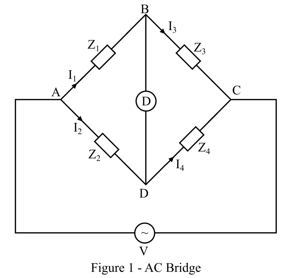
Based on the quantity to be measured by the AC Bridge, there are several types of Alternating current bridges like Maxwell’s Bridge, Hay’s Bridge, Anderson Bridge, etc. In this article, we shall focus on Wien’s Bridge only.
What is a Wien’s Bridge?
Coined after the scientist Max Karl Werner Wien, the Wien’s Bridge is a type of Alternating Current Bridge, comprised of four conducting wires connected to each other to form a bridge. The main objective of a Wien’s Bridge is to estimate the frequency ranging from 100 Hz to 100 kHz, with precision ranging between 0.1% and 0.5%. The frequency is usually denoted by the symbol f and is measured in Hertz (Hz).
Additionally, the bridge could also be used to measure the unknown value of capacitance in the bridge. The Wien’s Bridge is said to be balanced when the null indicator shows zero deflection. It can handle high-voltage power but is susceptible to large frequency values.
Construction of Wien’s Bridge
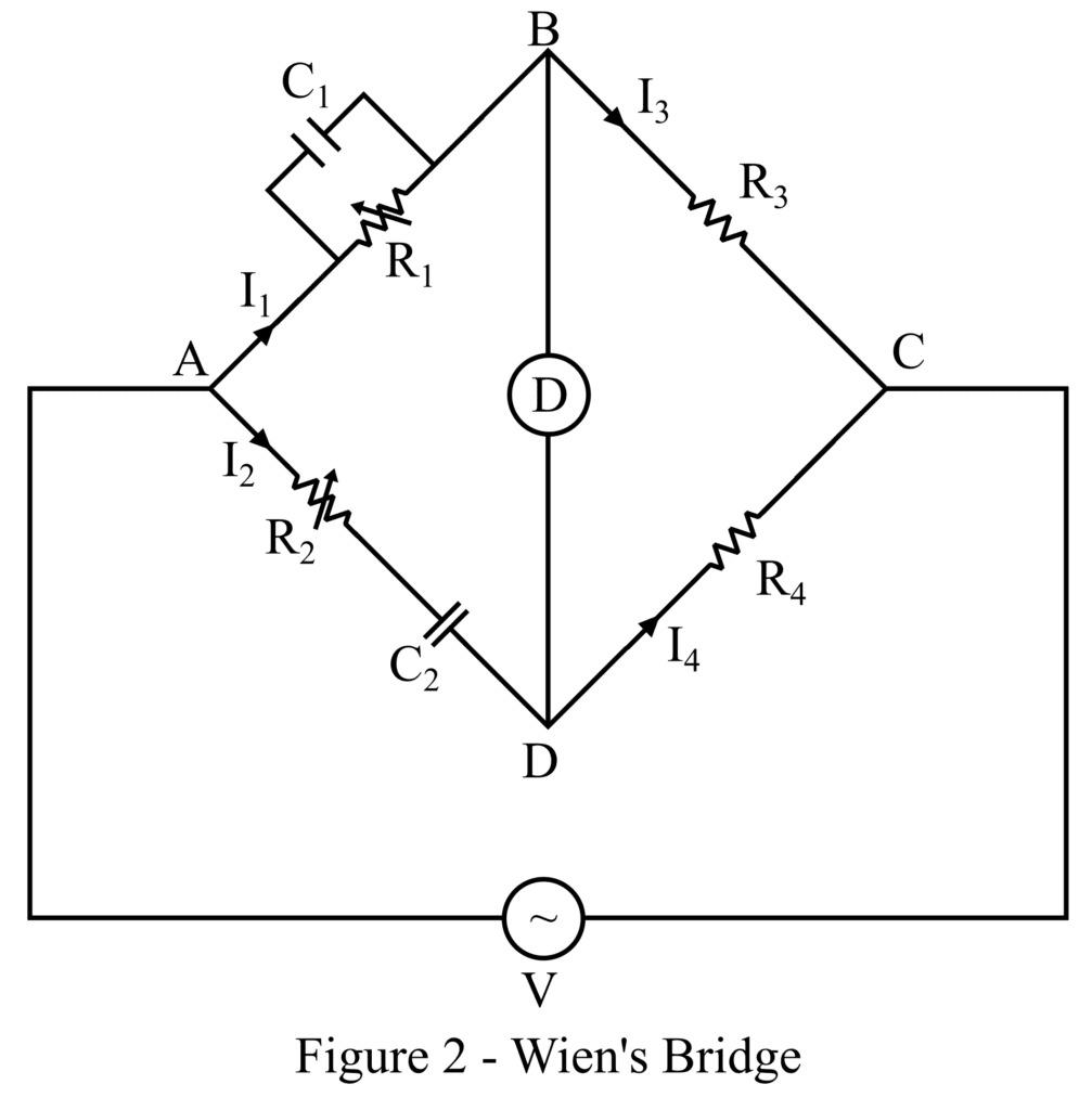
The bridge is constructed by connecting the four arms of the bridge together where a series arrangement of capacitor and resistor is in one arm, and a parallel arrangement of capacitor and resistor in the other. While a resistor is present in each of the two remaining arms. The circuit representation of Wien’s bridge is shown in Figure 2.
A null indicator represented by D is linked across the intersection points of B and D, and an AC voltage source is connected across the junction AC as shown in Figure 2 below. The deflector is used to keep the bridge in a balanced condition by ensuring that the voltage values at points B and D are equal.
Derivation of Frequency of Wien’s Bridge Circuit
Let,
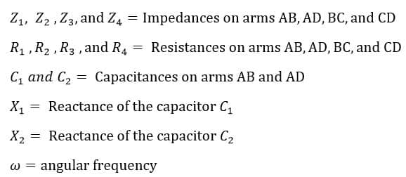
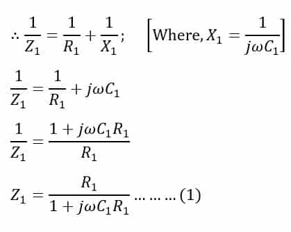
Impedance Z1 of arm AB is determined as follows:
Arm AB is comprised of resistor R1 connected in parallel with capacitor C1 as shown in Figure 2 above.
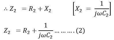
Impedance Z2 of arm AD is determined as follows:
Arm AD is comprised of resistor R2 connected in series with capacitor C2 as shown in Figure 2 above.
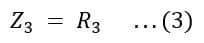
Impedance Z3 of arm AB is determined as follows:‘
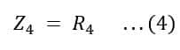
Impedance Z4 of arm AB is determined as follows:
Balanced bridge condition
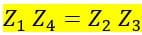
Mathematically, the balanced condition of the bridge is obtained by equating the products of impedance pairs Z1, Z4, and Z2, Z3 as follows:
Substituting the values of impedances Z1, Z2, Z3, and Z4 from equations (1), (2), (3), and (4):
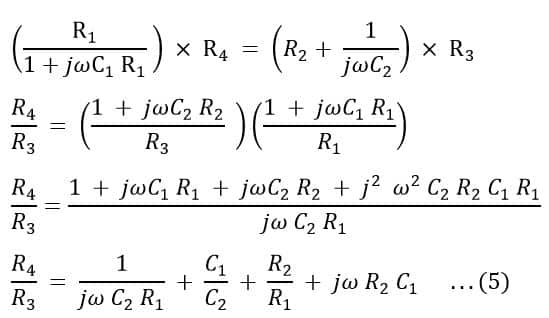
The next step is to equate the real and imaginary parts of the equation (5):
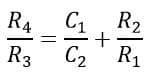
Equating real parts of the equation (5) on both sides:
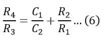
Equation (6) shows the relation between resistances R4 and R3.
Equating imaginary parts of the equation (5) on both sides:
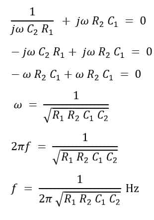
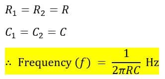
If components are selected such that the resistances and capacitances on arms AB and AD are equal by coupling the resistances R1 and R2 mechanically as follows
Advantages of the Wien’s Bridge
The Wien’s bridge has several advantages, some of which are listed below:
- Simple Circuitry: Wien’s bridge is formed using easily available electronic components namely resistors and capacitors.
- Cost-effective: Since all the components used to design Wien’s bridge are inexpensive, the cost of creating the circuit is meager for the manufacturers.
- Quantitative measurements: Wien’s bridge has the capability to measure the frequency and capacitance of the circuit with high accuracy.
Disadvantages of the Wien’s Bridge
There are also some disadvantages of Wien’s Bridge:
- Limited Frequency Generation: As Wien’s bridge is very sensitive to large frequency values and the circuit may get destructed at high-frequency values, hence the frequency generated by the bridge is limited between 100 Hz and 100 kHz.
- High Output distortion: Due to the susceptibility of the Wien’s bridge circuit to large frequency values, the resultant output signal is highly distorted.
- Not Purely Sinusoidal AC Input Voltage: Due to the presence of harmonic distortions at the input AC voltage source, the balance condition of the bridge is disrupted.
Applications of the Wien’s Bridge
The following are some applications of Wien’s bridge circuit:
- Wien’s bridge is used for the purpose of measuring the frequency of the input voltage and capacitance of the circuit.
- It is used for analyzing distortion due to harmonic disturbances.
- Wien’s bridge also finds its application as a high-frequency oscillator.
- It is also used for estimating the frequency values in audio and radio oscillators.
Conclusion
Hence, this is all about Wien’s bridge circuit. From the above discussion, we may conclude that Wien’s bridge is primarily used for the determination of the frequency of the voltage applied at the input side of the circuit, in addition to the measurement of the capacitance values present on the arms of the bridge. Despite some of the downsides of using Wien’s bridge, its wide range of applications and advantages outweighs the drawbacks posed by the electronic circuit.
Numerical Example on Wien’s Bridge
The four arms of a Wien’s bridge ABCD are supplied with the sinusoidal input voltage, having the following values:
Arm AB: A resistance, R1 = 200Ω in parallel with a capacitance (C1) valued at 1µF.
Arm BC: R3 = 400Ω
Arm CD: R4 = 1000Ω
Arm DA: Resistance R2 is in series with capacitance (C2) valued at 2µF
Determine the value of resistance R2 and the frequency at which the bridge will be in the balanced condition.
Solution-
Using equation (6) stating the relation between resistances R3 and R4, we have,
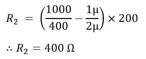
By rearranging the above equation, we get,
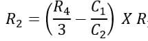
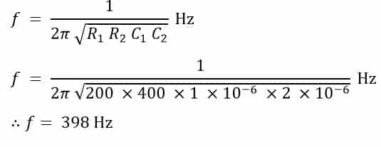
Substituting the values ofR1 = 200Ω; R3 = 400Ω; R4 = 1000Ω; C1 = 1 µF; C2 = 2 µF in the above equation, we get,
Next, to determine the frequency of the applied voltage use the formula given below: