In this article, we will discuss the working of center-tapped and bridge-type full-wave rectifiers. The full-wave rectifier converts AC voltage into DC voltage. It converts positive and negative cycles of AC voltage into DC voltage. The center tapped rectifier and bridge rectifier are two types of full-wave rectifiers.
What is full-wave rectifier?
A full-wave rectifier is a circuit that converts an alternating waveform signal to a pulsating DC signal. The process is termed full-wave rectification which converts AC signal to DC signal. The full-wave rectifier uses more multiple diodes to convert an input AC voltage to provide an output DC voltage.
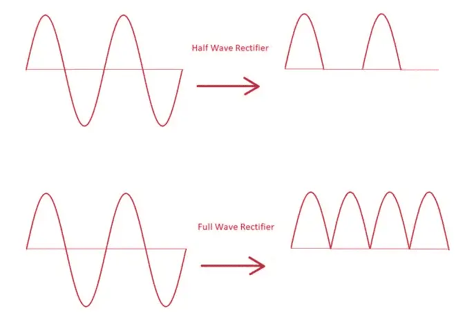
Rectifiers are of two types- Full-wave rectifiers and half-wave rectifiers. As discussed full-wave rectifier provides a pulsating DC signal from an input alternating signal. The full-wave rectifier converts the complete AC cycle into DC. While in the case of a half-wave rectifier, we receive only a half-wave of an alternating signal at the output end. Hence the efficiency of a half-wave rectifier is only near 40%.
Types Of full Wave Rectifier
There are two types of full-wave rectifiers.
- Center tap full wave rectifier
- Bridge Rectifier
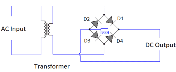
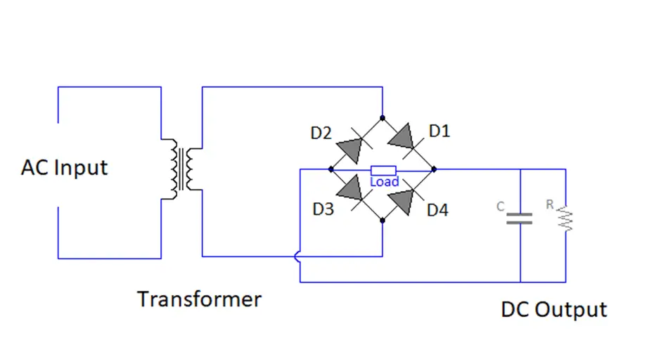
As seen in the above image, a full-wave rectifier has an AC input source, a transformer (generally step down only), and four diodes. The transformer used here is a normal transformer.
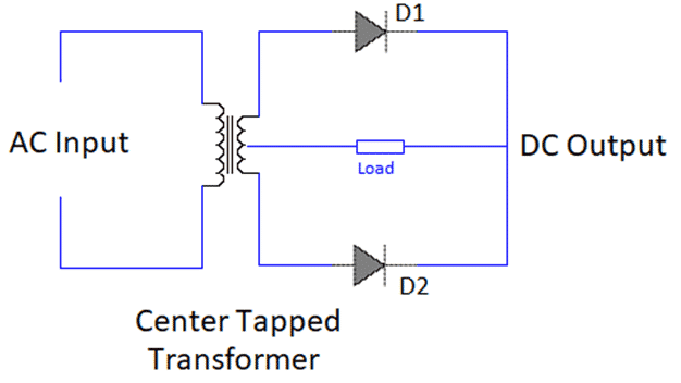
Another type of rectifier is a center tap full-wave rectifier. It uses a center-tapped transformer. The center-tapped transformer uses only two diodes.
Let us discuss in detail about center tapped full wave rectifier and full-wave rectifier.
Centre Tapped Full Wave Rectifier
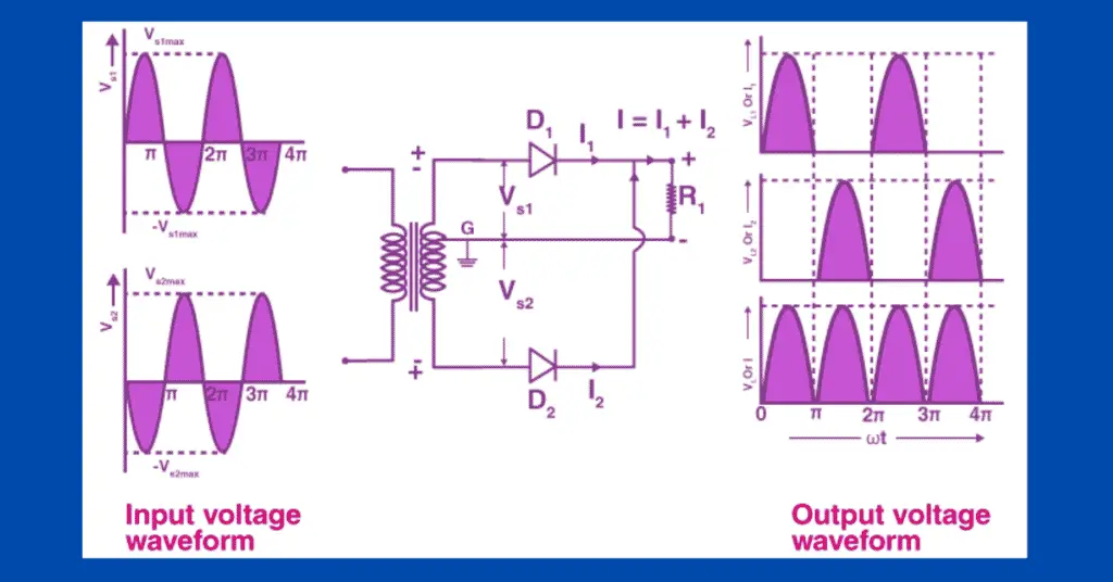
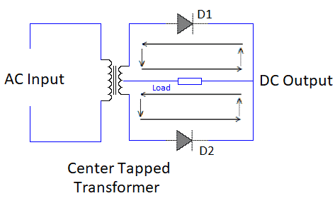
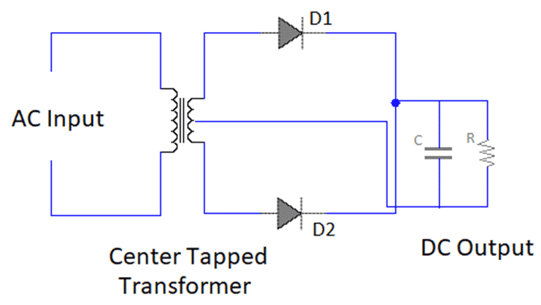
The center-tapped full-wave rectifier consists of a center-tapped transformer, two diodes, and a load. A center-tapped transformer is nothing but a normal transformer with a wire connected at the exact center of the secondary winding. The center wire of the secondary winding has zero potential. For example, the transformer with a center tap is specified as 15-0-15 volt. Here center tap is at zero potential and the other two points of the transformer change their polarity. Because of this type of construction, we get simultaneous alternating voltages on both sides. The polarity of the voltages will be totally opposite on both sides.
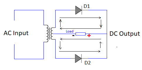
Working of Center-tapped full wave rectifier
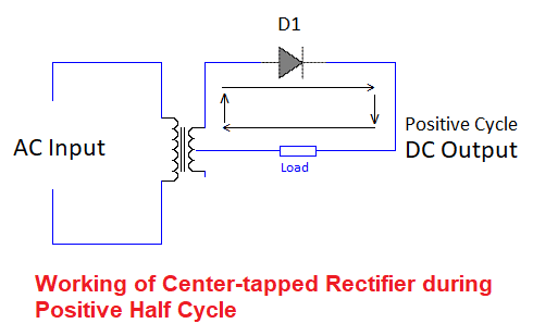
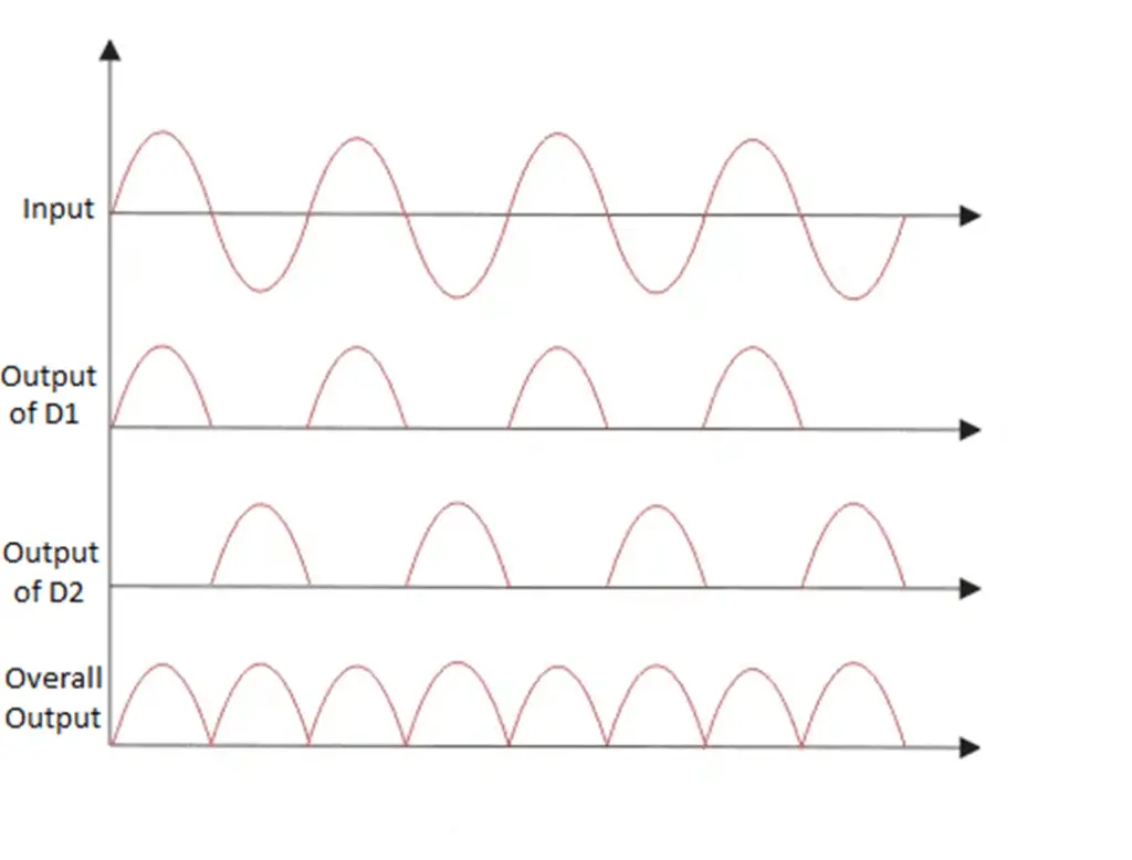
During the positive half cycle of the AC signal, Diode D1 is in forward biasing state while diode D2 is in reveres biasing state. So, diode D1 conducts and diode D2 does not conduct. So current will flow through D1 and D2 will not be in the picture while this cycle.
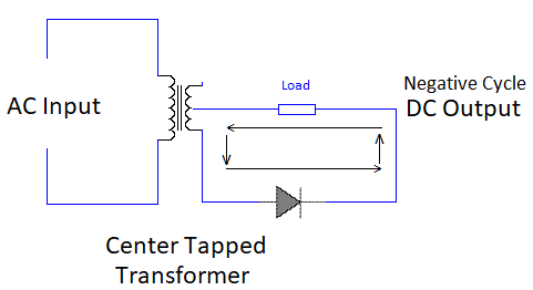
Now during negative positive half cycle of the AC signal, Diode D2 will be forward biased while diode D2 will be reverse biased. So D2 will be conducting and D1 will not be conducting. So current will flow through D2 and D1 will not be in picture while this cycle.
The below-shown picture shows the output waveform of the center-tapped full-wave rectifier.
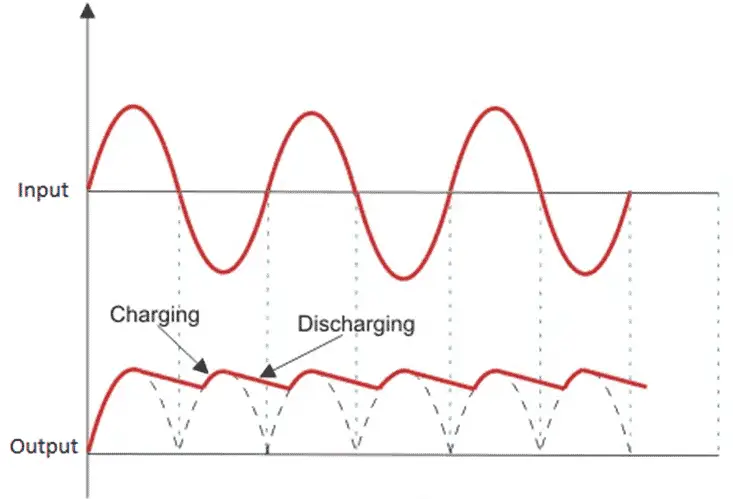
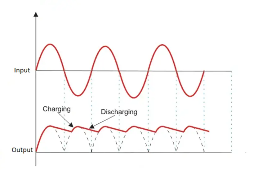
The circuit we used here, produces a pulsating DC waveform. Practically, this pulsating DC waveform is of no use. So, to make it smooth, a filter is used with the center-tapped full-wave rectifier we discussed. A capacitor and a resistor are used in this circuit to filter out the pulsating DC. The filter works as follows: when diode D1 is forward biased, the capacitor is charged through diode D1.
When the voltage reaches a peak, the capacitor is fully charged. Now as voltage starts decreasing, the capacitor starts supplying voltage to the load. Now the capacitor voltage will gradually decrease also, but discharge is a bit slow process than charging a capacitor. So, before the capacitor discharges, diode D2 will come in forward bias. This diode D2 will again charge the capacitor. This way this process of charging and discharging will continue and we get a smooth DC wave.
Filter circuit of Center tapped full wave bridge rectifier
Full Wave Bridge Rectifier
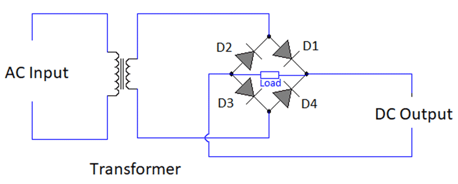
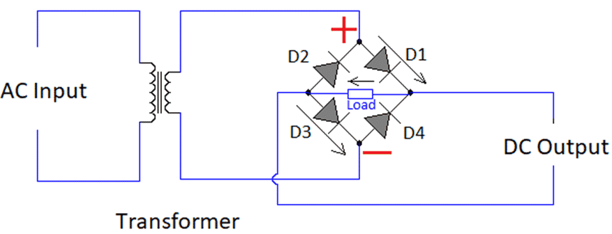
A full-wave bridge wave rectifier consists of a normal transformer compared to the center-tapped transformer used in the center-tapped full-wave rectifier. Hence the circuit used also changes. The circuit of a full-wave bridge rectifier consists of four diodes and a load connected to it.
Working of a Full Wave Bridge Rectifier
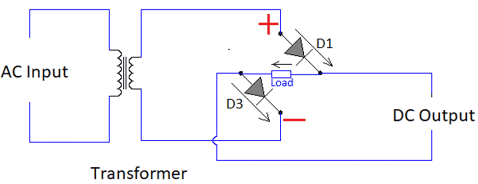
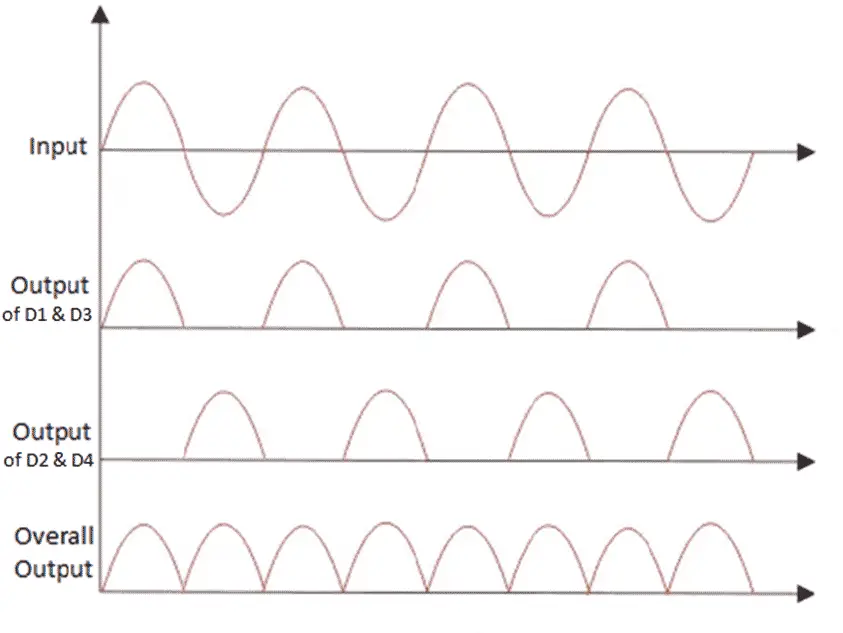
We can understand the working of a full-wave rectifier with a help of its circuit diagram. As seen from the diagram of the full-wave bridge rectifier, there are four diodes i.e. D1, D2, D3, and D4. During the positive cycle of the alternating waveform, diodes D1 and D3 are in forward biased. At this time, diodes D2 and D4 are in reverse bias. So, signal/voltage will flow from diodes D1 and D3 while diodes D2 and D4 will not be conducting.
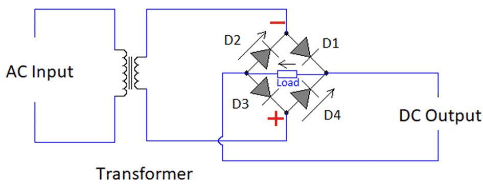
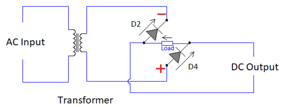
Now during the negative cycle of the alternating waveform, diodes D2 and D4 will be forward biased. At that time, diodes D1 and D3 will be in reverse bias. So, signal/voltage will flow from diodes D2 and D4 while diodes D1 and D3 will not be conducting. The combination of the output of both these cases gives us a full-wave rectified signal but with pulsating output.
Output waveform of full-wave bridge rectifier
The output waveform from the circuit of the full-wave bridge rectifier is as shown
Filter circuit of full-wave bridge rectifier
Here also to make the output pulsating DC to a smooth output waveform, we use a filter circuit. The filter circuit is the same as we used in the center-tapped full-wave.
Now let us see various formulas used for full-wave bridge rectifiers
Ripple Factor of a full-wave bridge rectifier (γ or r)
As we saw that a full-wave bridge rectifier has a filter circuit to convert the pulsating DC output to a smooth DC output. In this process of conversion, some of the AC components still exist on the output side. This undesirable AC component on the output side is termed a ripple. Now to make it a numerical or countable number, we use a term called ripple factor denoted by γ or r.
The formula for ripple factor is
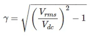
In the formula above, Vrms is the RMS value of the alternating input and Vdc is the output DC voltage. The ideal ripple factor for the center-tapped full-wave bridge rectifier is 0.48
Efficiency of a full-wave bridge rectifier
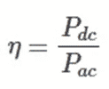
The efficiency of a full-wave bridge rectifier is the ratio of output DC to the input AC power. It is denoted by η.
The efficiency of a center-tapped full-wave rectifier is near 81.2%.
Form Factor of a full-wave bridge rectifier
The form factor of the full-wave bridge rectifier is the ratio of RMS value and average value.
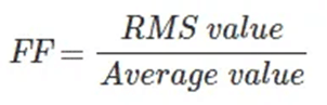
The form factor of a center-tapped full-wave rectifier is 1.11
Advantages of Full Wave Rectifier
- The efficiency of the full-wave rectifier is greater than that of the half-wave rectifier.
- The half-wave rectifier will have high ripples if a filter circuit is used. In the case of the full-wave rectifier, the waveform will be quite better with low power loss.
Disadvantages of Full Wave Rectifier
- The cost of the full-wave rectifier is high compared to a half-wave rectifier.
- Full-wave rectifier requires more space compared to a half-wave rectifier.