Computers installations small or big are susceptible to harmonics in the power lines. The advance designs of computer and peripherals make them virtually failure proof. But in presence of low quality power, containing harmonics brings down the life of equipment and subject them to premature failure. All the standard measuring instruments of AC current, voltage, power, power factor do not apply, as a result accessing the origin of failure is very difficult. The UPS has association on input as well as out harmonics problems practically all the peripherals have input rectifiers, which draw harmonic currents. Out put of the UPS uses filters, special switching algorithms to overcome bad effects. A unilateral clamp of % harmonics on either side of the UPS results into high costs.
There is a natural growth of harmonics in the electrical loads of a modern facility as it uses advance electronic equipment like communications, computers, servers etc. These equipment work on internal DC power supplies derived from AC mains available. All these loads take non-linear currents from the supply and generate harmonics in the supply. For continuity of the communications, holding on to the programs and data, UPS systems commonly used. There are three types of UPS systems in use namely off line, line iterative and on line. In off line and line interactive UPS system, AC mains when available, directly connected with no frequency and harmonic correction, hence harmonics present in mains are passed on to loads. Similarly the load harmonic currents are passed on to incoming line without any filtering.
The online UPS systems, which effectively act as a buffer for harmonics between load and power supply. Apart from providing uninterrupted power, because of these buffering action they are preferred by practically all the electronic applications.
UPS systems are associated with harmonic problems as well as solutions. There are different types and intensity of harmonic problems exists based on power ratings. The UPS systems broadly divided into following range
1. Micro UPS (Less than 3 KVA)
2. Low power UPS (3 – 20 KVA)
3. Medium Power UPS (20 – 100 KVA)
4. High Power UPS (Above 100 KVA)
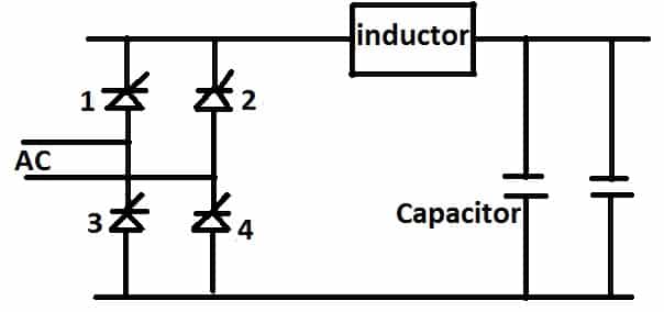
Starting with single-phase rectifier with diodes and filters capacitors used to power inverter the current drawn are very peaky. When controlled rectifier are used to power both powering
Inverter and charging battery, batteries are floated across the common Dc bus shared by inverter. The current drawn are non linear and contains harmonics.

Consider simple block schematic common to practically all types of UPS system online. The rectifier of UPS system shown in the above figure is connected to primary power input source. In most of the cases, the input source is commercial Ac power supply available. In the situation of power shortage, all the critical installations are supported by diesel generating sets, which come on and supply AC power to UPS systems. The rectifier of the UPS system consists of controlled devices and filters. There are number of variety of rectifier circuits and configurations used based on power requirement. The harmonic problem is prominent in medium and high power UPS in all rectifier configuration used.
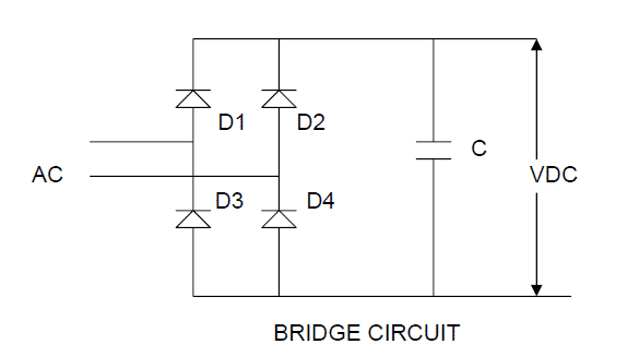
During positive cycle of AC wave form diode D1 and D4 gets forward biased and current flows from the source to diode D1, D4 and capacitor and return to mains. Similarly, during negative cycle the current flows from the source to diode D2, D3, and capacitor and return to mains. Thus the direction of the current in the capacitor remains unidirectional during complete cycle of alternating current. 5 KVA and above many of the UPS systems use the thyristor type of rectifiers. Up to 10 KVA single phase rectifier is used, whereas above 10 KVA 3 phase rectifier is used.
For medium power rectifiers in the UPS use 6 pulse converters in major way. The 6 pulse have been well documented harmonic behavior pattern. UPS rectifiers use filters on DC side and has battery as back EMF. This is similar to DC drive situation. In most of the cases the rectifier operates in discontinuous current mode, take peak currents and have harmonics ranging from 15 to 40 %. There is added seriousness to harmonic problems in Indian conditions wherein the input voltage variation is very wide, high input impedance and wide frequency fluctuation experienced. Because of these problems to make 6-pulse rectifier with harmonic traps to keep 5 % input current is a techno commercial challenge.
SOLUTION FOR CONTROLLING UPSTREAM HARMONICS
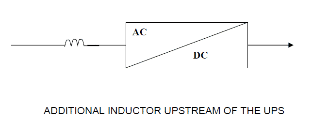
1. INDUCTOR ON THE RECTIFIER INPUT
It consists smoothing inductor upstream of the UPS rectifier thus adding to the total inductance of the source. The disadvantage with use of inductor is that line voltage drop occurs in the inductor.
2. LC PASSIVE FILTER
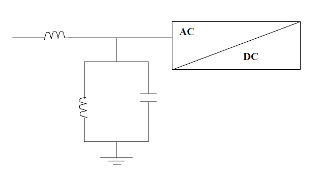
This solution consists in installing in additional to a smoothing inductor, an LC filter in parallel on the rectifier / charger input. The value of L and C are selected such that the filter impedance is zero for the 5 thharmonic current (the most significant) and low for 7th harmonic current. To that end values are selected such that LCw2 = 1 for H5 i.e. f = 5 x50 = 250 Hz. Thus for
- The fifth harmonic order (250 Hz), the parallel impedance is equal to zero. The entire fifth harmonic current flows through the parallel circuit and no longer effects the other loads.
- The seventh harmonic order (350 Hz 0 given the slight shift in tuning, the parallel impedance is still low and part of H7 current is also eliminated.
- The harmonics with higher orders, the parallel impedance of the filter is very close to that of its series inductor and it operates as voltage divider.
ADVANTAGES:
1. Simple and reliable solution
2. The inductor can be added to the installation at any time.
3. Increase in the input power factor. The presence of the parallel filter circuit tuned to fifth harmonics cause a capacitive current to appear at the fundamental frequency. This capacitive current may, thus improve the power factor of the rectifier.
DISADVANTAGES:
1. Limited spectrum. This solution is effective only for frequencies closed to the tuned frequency. It eliminates the fifth harmonic current, a part of seventh harmonic,but very little of H11 and H13.
2. Poorly suited to change in the load level. Effectiveness is cut in half when the UPS operates at 50 % load.
3. Dependence on the source. If the installation includes an engine generator set, the basic filter may not be used if the engine generator set cannot accept a capacitive current equals to 30 % of the rectifier current. In this case compensated filter is required.
PULSE FILTER
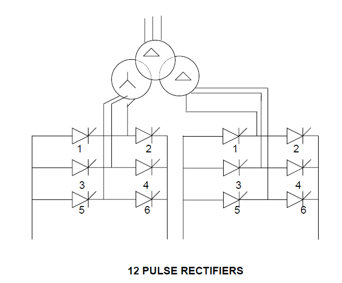
This solution, for which UPS SYSTEMS was one of the precursors back in 1975,may be used for both single and parallel UPS systems. It uses (see figure 8) a transformer with two secondary winding to supply voltages with a 30% phase shift, each of the secondary supplying a Gretzky-bridge rectifier. The result is 12-pulse rectification because the double bridge has twelve legs.The rectifiers must supply identical DC currents to ensure that the AC currents drawn on the transformer secondary have the same values. In this manner, the harmonic currents generated by each of the rectifiers on the primary of the transformer are recombined.
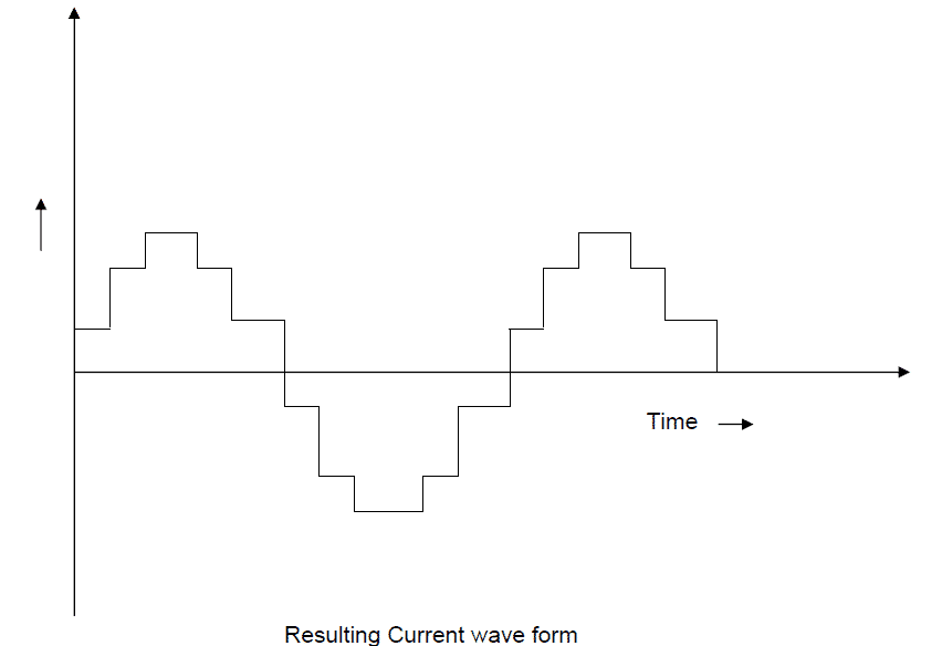
The selected phase shift reduces harmonic orders 6k+_1(where k is a whole number) and only orders 12k+_1 remain. Harmonic orders H5.H7, H17 and H19 are thus eliminated. Harmonic orders H11, H13, H23 and H25 remain.The resulting current has a waveform that better resembles a sinusoidal current that obtained by a single rectifier.
The resultant current at the input of transformer is more sinusoidal compared to six pulse rectifier and the waveform of current (input Current) is as given below.
DIFFERENT VERSIONS
1. Double bridge and transformer with two secondary.
2. Double bridge and autotransformer.
3. Series or parallel connection of the rectifier
ADVANTAGES
1. Acceptable performances, but less than that of passive filters: THDI<=10%.
2. Complete galvanic isolation at the UPS input for versions with transformers such as those proposed by UPS SYSTEMS.
DISADVANTAGES
1. Must be planned from the installation design stage 2. Complex (balanced voltages, short circuit currents, rectifier currents).
2. Expensive (double rectifier, transformer with double secondary or autotransformer).
3. Poorly suited to changes in the load level. Effectiveness drops with the percent load (the THDI rises from 10% at full load to 15% to 50% load).
4. Not complaint with guide IEC 61000-3-4
ACTIVE CONDITIONER
Operating principle
UPS SYSTEM introduced this topology in 1997,where in the rectifier is similar to dual bridge in configuration, however with some differences, the active conditioner includes a fully rated 6-pulse IGBT bridge actively compensates/cancels the re-injected current harmonics.
Active conditioner offers following advantages.
1. Elimination of harmonics (THDI<5%)
2. An increase in the power factor up to PF>0.94
3. A virtually constant level of performance from 30 to 100% load, whatever the type of source.
4. Total freedom in the installation because the absence of upstream harmonics means no more special precautions is required.
5. Total compatibility with engine generator sets even at low load levels which in turn reduces the risk of
a) Disturbing engine generator set operation (temperature rise, disturbed regulation etc.)
b) Increased voltage distortion due to the higher source impedance (the sub transient reactance X”d of an engine generator set is approximately 10 to 12%as compared to 3 to 4% for the short circuit voltage Uscx of a transformer) 6.Up to 15% reduction in consumption with a corresponding optimization of the upstream cables,transformer and engine generator set. The kVA drawn at the input are less than the output kVA;
a) The input power factor is >0.95, with the current and voltage maintained in phase by the regulation system, and the o/p power factor during normal operation is 0.8
b) A UPS with 200 KVA of apparent output power (i.e. 160 kw where PF=0.8) consumes (given 93%)
-With a traditional rectifier (input pf=0.8): s=(160/0.91))/0.5=215 KVA
– With a active pulse rectifier: S’=(160/0.91)/0.94=187 KVA i.e. a reduction of
(S-S’): S =(215-187)/215=13%
6. Total compliance with the IEC 61000-3-4 guide. The THDI <4% means the main harmonics are under 3%.Infact the individual level for all harmonic orders is significantly less than the requirements contained in the IEC 61000-3-4 guide
COMPARISON OF SOLUTIONS
THM approach
UPS SYSTEM proposes an overall approach to controlling harmonics in the framework of THM (total harmonic management).
This approach starts with an on-site audit of the customer’s installation followed by proposed solutions precisely suited to customer’s operating goals.
For UPSs, this approach makes it possible either to guarantee a desired level of harmonic compatibility or to eliminate harmonics. To that end and depending on needs of customers, UPS SYSTEMS can propose the entire range of solutions presented in the preceding pages.
Harmonics problems at UPS output
As seen from the block schematic in fig.1 there is no carry through harmonics comes at UPS output from the input supply whatsoever distorted, since there is s DC link with battery. The inverter in the UPS generates output sine wave three phase or single-phase voltages. IGBT inverters use one of the common techniques of the sine wave pulse width modulation (PWM).
There are very few low-end applications use semi square wave inverters, which contain high harmonics in generation itself these types are not considered for this paper.
The figure shows control in block schematic form, there is an internal pure sine wave reference generated with distortion less than 0.1% the UPS output waveform is compared and the pulse width is adjusted. This happens at more than 20 times in a power cycle ever, hence output waveform is corrected to very precise steps resulting in a good sine wave.
The modulation frequency used varies depending on KVA range, for practical reasons of noise, device limitations etc. Micro UPS use frequencies above 20 kHz, low power UPS 10 to 20 kHz, the medium power UPS uses frequencies between 1 to 5 kHz. In all the inverters simple L and C filtering is used to remove residual modulation frequency harmonics and voltage waveforms obtained are pure sine wave with harmonics less than 2-5 % or so Industry standard for all the applications.
As in case of mains the nonlinear loads draw harmonic currents when these interact with series L of the inverter output filter harmonic voltages are produced at UPS output. These get applied to other loads at the point of the common coupling (as specified by IEEE) which is nothing but UPS output point for all practical purpose. The known ill effects of presence of harmonics are there, some of them are seen easily others create premature component failures which cannot be traced to any apparent cause. All the known bad effects exist like heating in capacitors, transformers, motors etc. Standard procedure to distribute load at 3 phase UPS so that the neutral current remain low does not solve neutral current ill effects in presence of harmonics drawn by load. Special care has to be taken to limit neutral voltage 3 volts .the limits has come from usage of high speed 3.3 volt working semiconductor chips .The neutral current becomes 3 times the phase current, results in to high ground to neutral voltage and exceeds handling equipment limit of 3 to 5 volts in turn results in unreliable operations.
CONCLUSIONS
Clearly, two types of solutions stand out
1.The low cost solutions offering average performance.
These solutions implement a standard passive filter.
1. It is possible to reinforce the solutions depending on the installation (compensated filters or non-compensated filters with contactor)
2.The high performance solutions, which are marginally expensive in the initial investments, however reduce the TCO (total cost of ownership) and most importantly are compliant with the recommendations of the IEC 61000-3-4 guide.
These two solutions are:
a) “Clean power factor corrected” rectifier
b) Active harmonics rectifier to compensate the harmonics generated by 6 pulse graetz bridge
The many advantages provided by the PFC & active conditioner solutions at a relatively low TCO make traditional solutions at a relatively low TCO makes traditional 12 pulse solutions, for which MGE UPS was one of the pioneers back in 1975,virtually obsolete. Moreover these solutions do not respect the recommendations of the IEC 61000-3-4 guide.