In this article, we will discuss Owen’s Bridge, its circuit construction, equation, phasor diagram, advantages, and disadvantages. So let us start with the basic introduction of Owen’s bridge.
What is Owen’s Bridge?
Owen’s bridge is an AC bridge that is used for the measurement of self-inductance. The working principle of Owen’s bridge is based on the fact that the unknown inductance of an inductor is determined by comparing it with a standard capacitor. Hence, Owen’s bridge gives the inductance value in terms of capacitance. It is a balance bridge, i.e. the inductance value is determined by balancing the loads on its four arms.
Circuit Construction of Owen’s Bridge
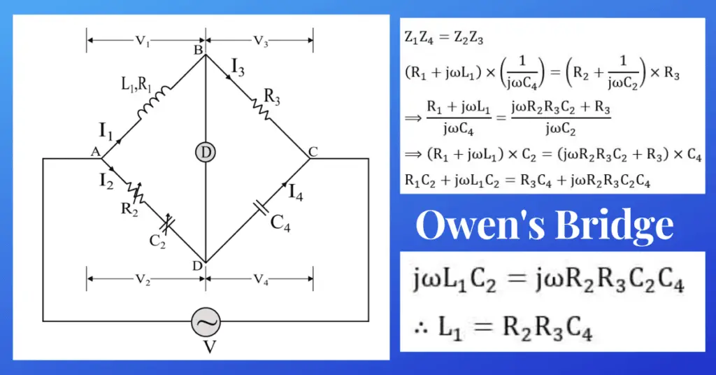
The circuit construction of Owen’s bridge for the measurement of inductance is shown in Figure 1.
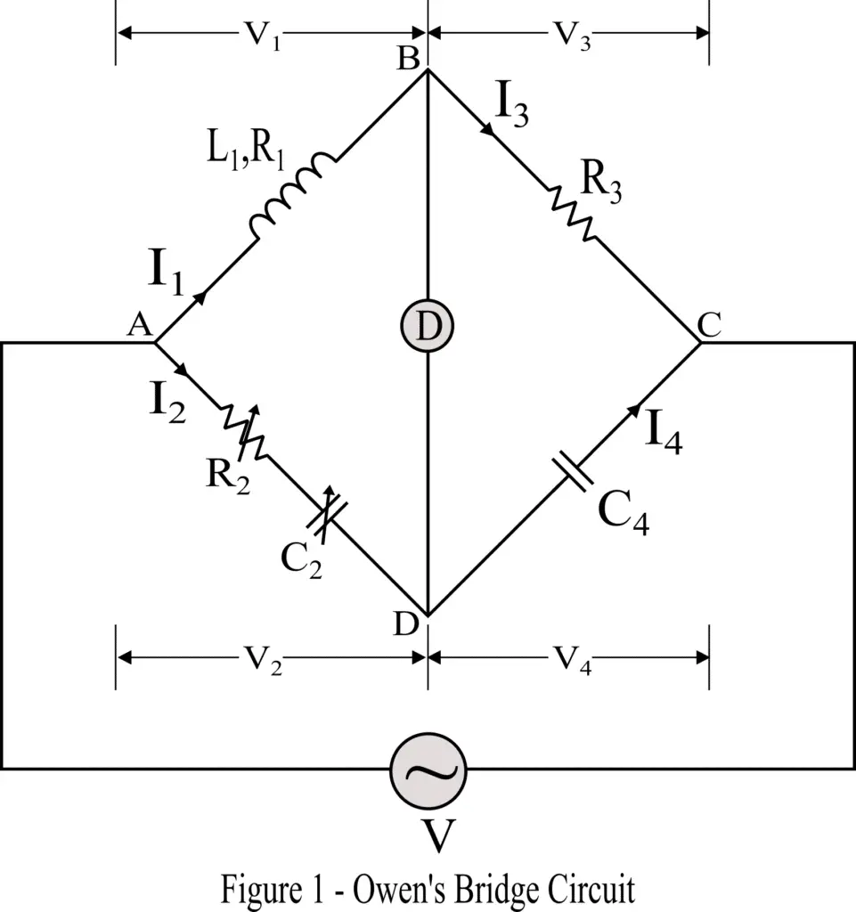
The bridge consists of four arms, where arm AB has an inductor L1 whose inductance is to be measured. The resistance of this unknown inductor is considered R1. The arm AD consists of a standard variable resistor R2 and a variable capacitor C2. The arm BC has a standard resistor R4, and the arm CD has a standard capacitor C4. Also, a null deflection detector is connected between nodes B and D, to determine the balance condition of the bridge.
Theory of Owen’s Bridge
The bridge is said to be balanced when the detector shows a null deflection. It is because, under the balanced condition of the bridge, the nodes B and D are at the same electric potential, consequently, there is no current flow through the detector.
The balance condition of the bridge is obtained by varying the standard variable resistor R2 and C2 in branch AD.
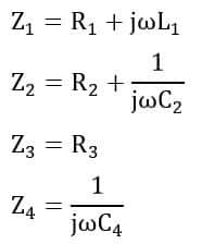
From the circuit diagram shown in the above figure-1, the impedances of arms are given by,
Under the balance condition of the bridge, we get,
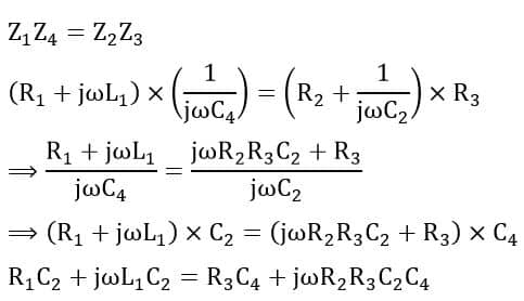
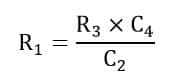
On equating the real and imaginary parts of the above equation, we have,
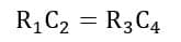
Therefore, the resistance of the inductor is,
And the inductance of the inductor is,
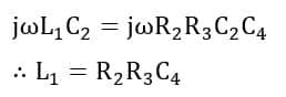
Hence, using the above equation of Owen’s bridge, the inductance of an unknown inductor can be determined by comparing it with a standard capacitor.
Phasor Diagram of Owen’s Bridge
We can draw the phasor diagram by using the relationship among voltage drops across and currents through each branch of the bridge. The typical phasor diagram of Owen’s bridge is shown in Figure 2.
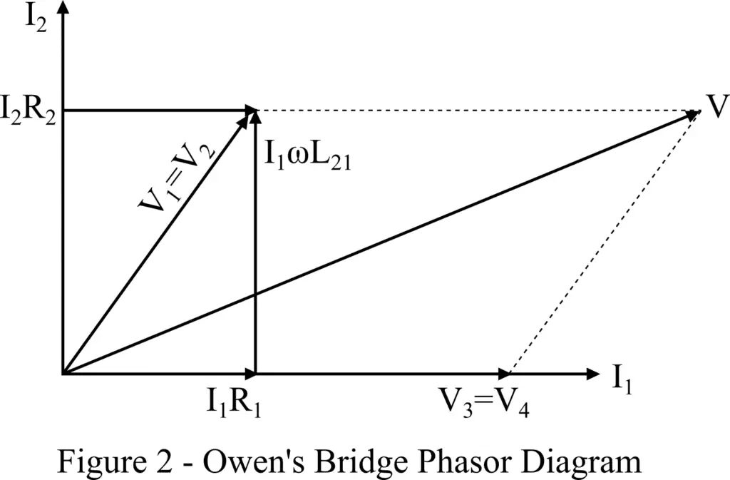
In the above phasor diagram, I1, V3, and V4 all are in the same phase as represented on the horizontal axis. The voltage I1R1 is also in phase with the current I1.
The voltage drop V1 across arm AB is the phasor sum of the inductive voltage drop ωI1L1 and the voltage drop I1R1. Under the balanced condition of the bridge, the voltages V1 and V2 across the branches AB and AD are equal.
The voltage drop V2 is the phasor sum of the voltage drops I2R2 and I2/ωC2. The supply voltage is equal to the sum of the voltages V1 and V3.
Advantages of Owen’s Bridge
The following are the major advantages of the inductance measurement-
- The derivation for the balance equation is quite simple.
- The balance equation of Owen’s bridge does not contain any frequency component.
- It can be used to measure the inductances of a wide range of values.
Disadvantages of Owen’s Bridge
The major disadvantages are listed below-
- The cost of Owen’s bridge is comparatively high due to the presence of an expensive standard capacitor.
- The accuracy of the standard variable capacitor is about 1%.
- For the high Q-factor, it requires large value of the capacitor C2.