In this article, we will discuss electrical transmission towers, their types, designs, and their different parts. The transmission tower is a part of a power transmission system that helps to transmit bulk power from generating stations to various grid substations.
What is a Transmission Tower?
A transmission tower supports an overhead power line. The other names of transmission towers are power transmission towers, power towers, and electricity pylons. The transmission towers carry high-voltage transmission line to transport power from the generating station to electrical substations. The electrical substations transport power to the end users through distribution lines. The distribution line uses utility poles to carry the low-voltage conductor.
Transmission towers have to carry the heavy transmission conductors at a sufficient safe height from the ground. In addition to that, all towers have to sustain all kinds of natural calamities. Therefore, the transmission tower design is an important engineering job where civil, mechanical, and electrical engineering concepts are equally applicable.
In order to decrease the transmission losses, after the generation of power, we step-up the voltage in order to transmit it over a long distance. At receiving end, we again step down the voltage value and use it for electrical loads. There are various transmission lines at various voltage levels throughout the power system network in order to transmit the bulk power.
A transmission tower (usually a steel lattice tower) supports the overhead power line. Transmission towers have to carry the heavy transmission conductors at a sufficient safe height from the ground depending on the voltage (132kV/220kv/400kv/765kv). Thus, the transmission towers maintain the minimum ground clearance according to the system voltage.
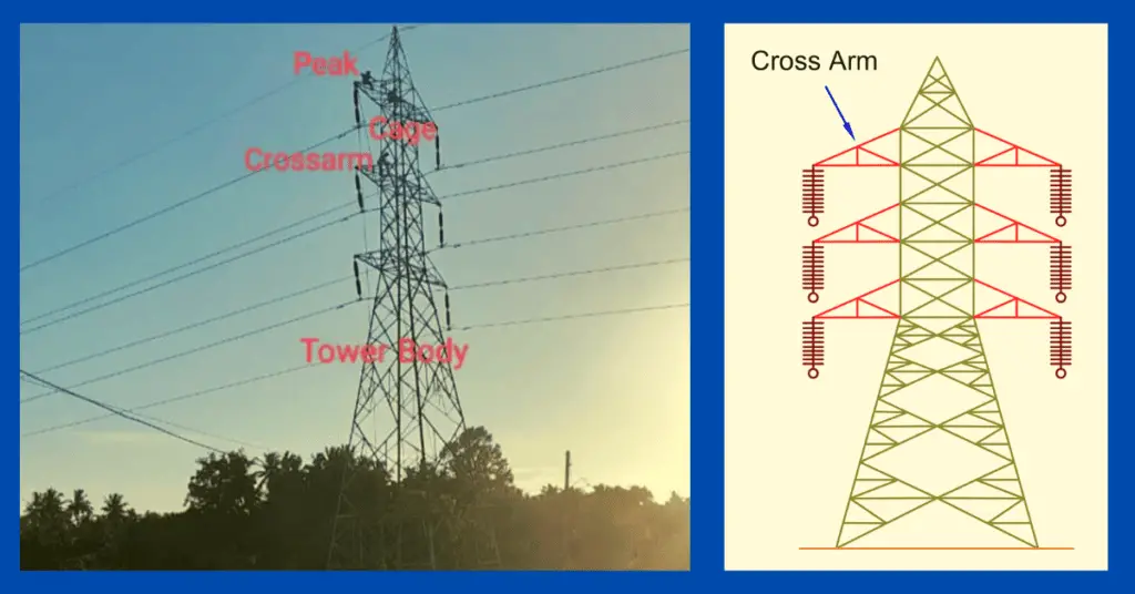
Parts of Transmission Tower
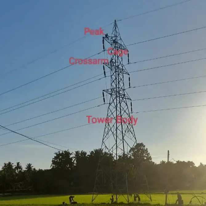
An EHT transmission tower consists of the following parts:
- The peak of the tower(the portion above the top cross arm)
- The cross arm (Cross arms of the transmission tower hold the transmission conductor)
- Cage of transmission tower(portion between tower body and the peak is known as a cage of transmission tower)
- Transmission Tower Body(The portion from the bottom cross arms up to the ground level)
- Leg of transmission tower
- Stub/Anchor Bolt and Base plate assembly of the transmission tower.
The description of each part is given below.
Peak of Transmission Tower
The top portion of the transmission tower is called the peak of the transmission tower.
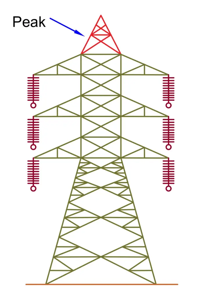
It is situated above the top cross arm, and it carries an earth shield wire connected to the tip of the tower’s peak.
Cross Arm of Transmission Tower
Cross arms hold the transmission conductors. The size of the cross arms is different for the transmission of various voltages.
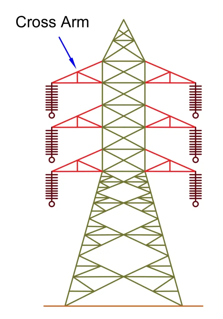
The dimension of the cross arm depends on the following parameters.
- Configuration of tower
- Level of Transmission Voltage
- Minimum forming angle for stress distribution.
Cage of Transmission Tower
The part of the tower between the tower body and peak is known as the cage of the transmission tower. The cage holds the cross arms.
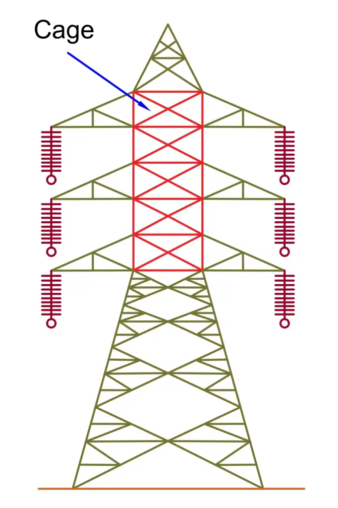
The shape of the cage may be a square or triangle, depending on the height of the tower.
Transmission Tower Body
The spacing between the lowest cross arm of the tower and the ground is called the transmission tower body.
The transmission tower body provides the height of the tower required for ground clearance.
Leg of transmission tower
The transmission tower stands on its leg. There may be one, two, or more legs according to the requirement of the tower structure.
Stub/Anchor Bolt and Base plate assembly
This part holds the entire structure of the tower.
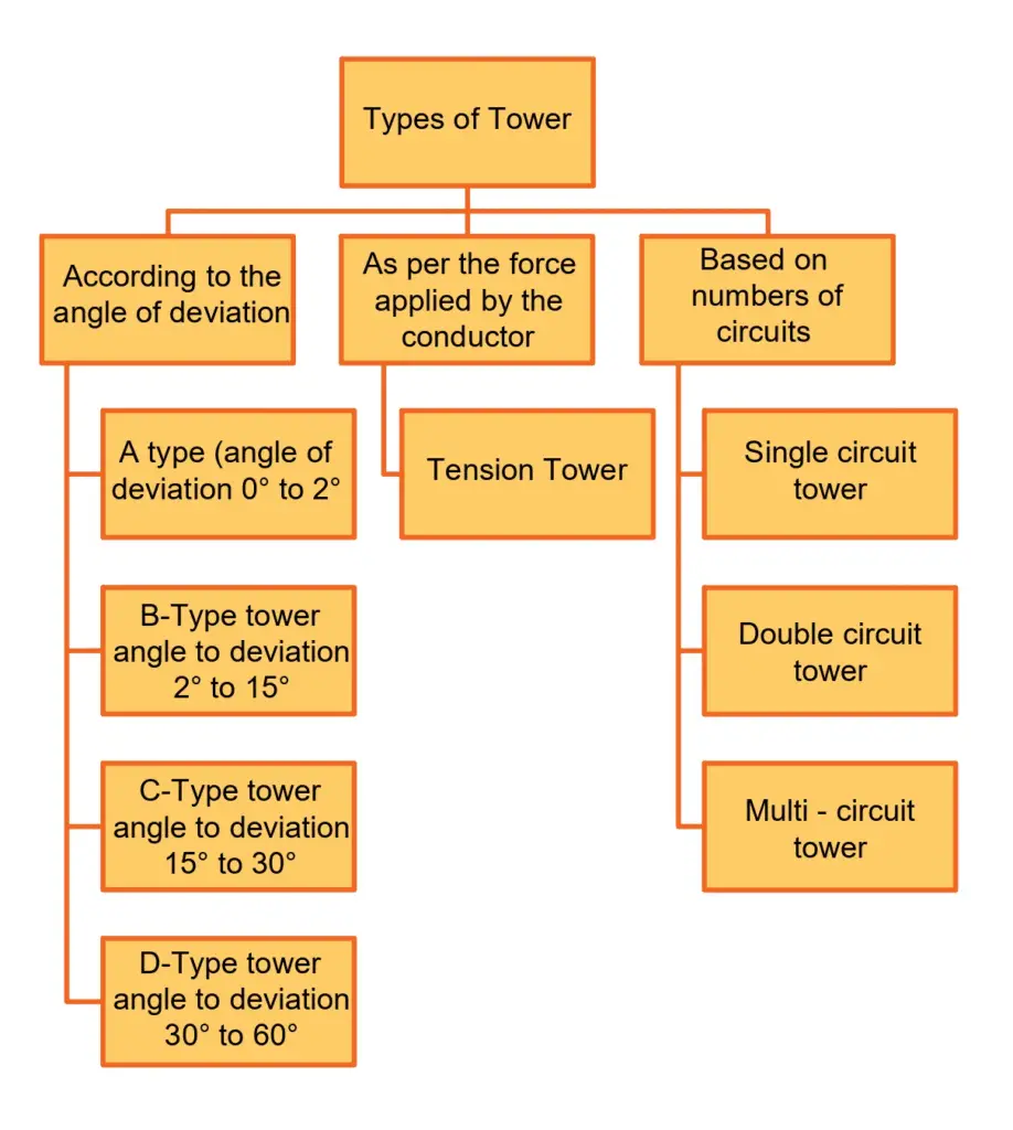
Types of Electrical Transmission Towers
According to different considerations, There are various types of transmission towers, depending on different considerations. The transmission line design depends on the available corridors. The transmission line needs to deviate from its shortest route in the case of obstruction. Thus, there may be several deviation points. The different types of towers are used as per the angle of deviation.
There are four types of transmission towers according to the angle of deviation.
| Type of Tower | Angle of Deviation |
| A- Type | 0o to 2o. |
| B- Type | 2o to 15o |
| C-Type | 15o to 30o. |
| D-Type | 30o to 60o. |
The broad classification of the transmission towers is shown in the below picture.
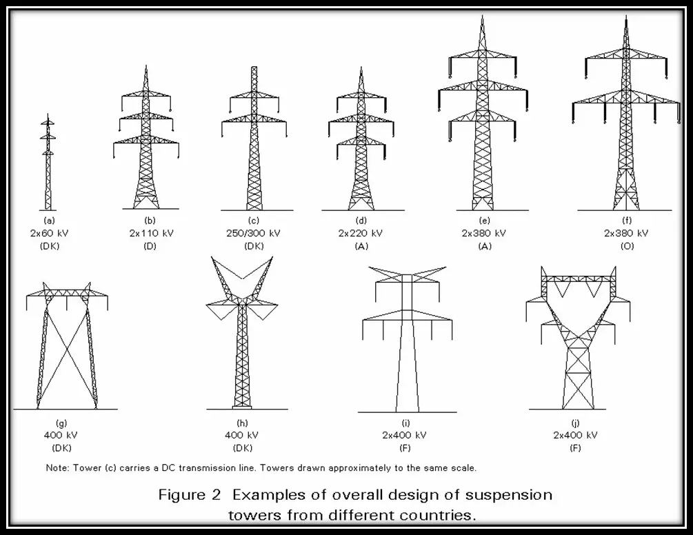
High Voltage Alternating Current transmission lines are used for extra-high voltage (110- or 115-kV and above; most often 132- or 220-kV and above in contemporary systems) AC transmission lines. The towers are designed in such a way that they can safely carry three (or multiples of three) conductors.
High-voltage direct current (HVDC) transmission lines are either monopole or bipolar systems.
| HVDC transmission | |
| bipolar systems | a conductor arrangement with one conductor on each side of the tower |
| single-pole with ground return | only one conductor can be used |
The railway overhead line has single-phase AC railway traction lines. The construction of the lines is similar to the construction of 132 kV three-phase lines. These lines can be constructed by use of steel tubes or concrete poles. According to different considerations, there are different types of transmission towers as shown in figure 2.
Apart from the above-customized type of tower, the tower is designed to meet special usages (Special Type Tower) listed below:
- River crossing tower
- Railway/ Highway crossing tower
- Transposition tower
Storms, ice, earthquakes, flooding, soil erosion, and willful acts can all cause damage or destroy towers. The emergency restoration system structures are designed to rapidly get lines back in service by quickly and safely bypassing damaged permanent structures. The emergency restoration system (ERS) structures allow you to rebuild or replace permanent structures without time constraints.
Transmission Tower Design
There are various designs for transmission structures. Two common types are:
Lattice Steel Towers (LST)
It consists of a steel framework of individual structural components that are bolted or welded together
Tubular Steel Poles (TSP)
It consists of hollow steel poles fabricated either as one piece or as several pieces fitted together.
The basic specifications to be considered before the design of the tower is mentioned below.
- Voltage
- The number of circuits.
- Type of conductors.
- Type of insulators.
- The possible future addition of new circuits.
- Tracing of the transmission line.
- Selection of tower sites.
- Selection of rigid points.
- Selection of conductor configuration.
- Selection of height for each tower.
Selection of height of Tower.
The tower design philosophy mainly considers the factors of the tower height, base width, top damper width, and cross arm’s length.
Typical tower height is in the range of 15 to 55 m (49 to 180 ft).
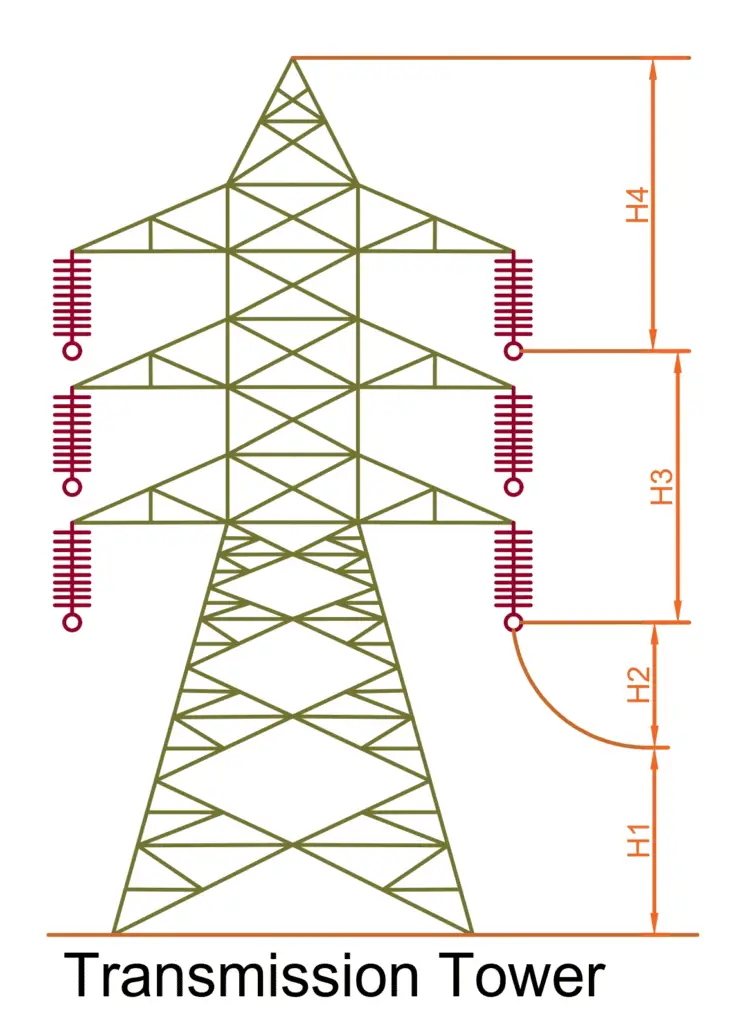
The height of the tower is determined by-
H=H1+H2+H3+H4
where,
H1 =Minimum permissible ground clearance;
H2 =Maximum sag;
H3 =Vertical spacing between conductors;
H4 =Vertical spacing between earth wire and top conductor.
Minimum permissible ground clearance
Normally minimum ground clearance in an Electrical power transmission line varies depending on the voltage level.
Maximum Sag
Sag Template is a tool with the help of which the position of towers on the profile is decided so that they conform to the limitations of vertical and wind loads on any particular tower, as per I.E. Rules.
Vertical spacing between conductors
The vertical space between power conductors plays an important role in spacing between the cross arms.
Vertical clearance between earth wire and top conductor
The main factors which affect determining the location of the earth wire on the transmission tower are the minimum difference in
- Suspension insulator length
- The drop of earth wire to Suspension clamps
- Angle of shield
Summary
The overall design of each tower is very closely connected with the user’s functional requirements. The requirements must be studied carefully before erection and commissioning.
Excellent