In this article, we will discuss Anderson’s Bridge in electrical measurement. Here, we will cover the circuit diagram, equation, phasor diagram, and advantages and disadvantages of Anderson’s Bridge.
What is Anderson’s Bridge?
In electrical measurement, Anderson’s Bridge is a circuit that is used to determine the self-inductance of the circuit. It is a type of AC (alternating current) bridge. Anderson’s Bridge for the measurement of inductance is one of the most common and best bridges for precise measurement of inductance over a wide range. In the case of Anderson’s bridge, the self-inductance is measured in terms of a standard capacitor.
Anderson’s bridge is basically a modified form of Maxwell’s bridge that is used for the measurement of self-inductance of low Q coils(Q<1). The key difference between Anderson’s bridge and Maxwell’s bridge is that Anderson’s bridge uses a fixed capacitor instead of a variable capacitor. Therefore, Anderson’s bridge gives more accurate results as compared to Maxwell’s bridge.
Circuit Constructions of Anderson’s Bridge
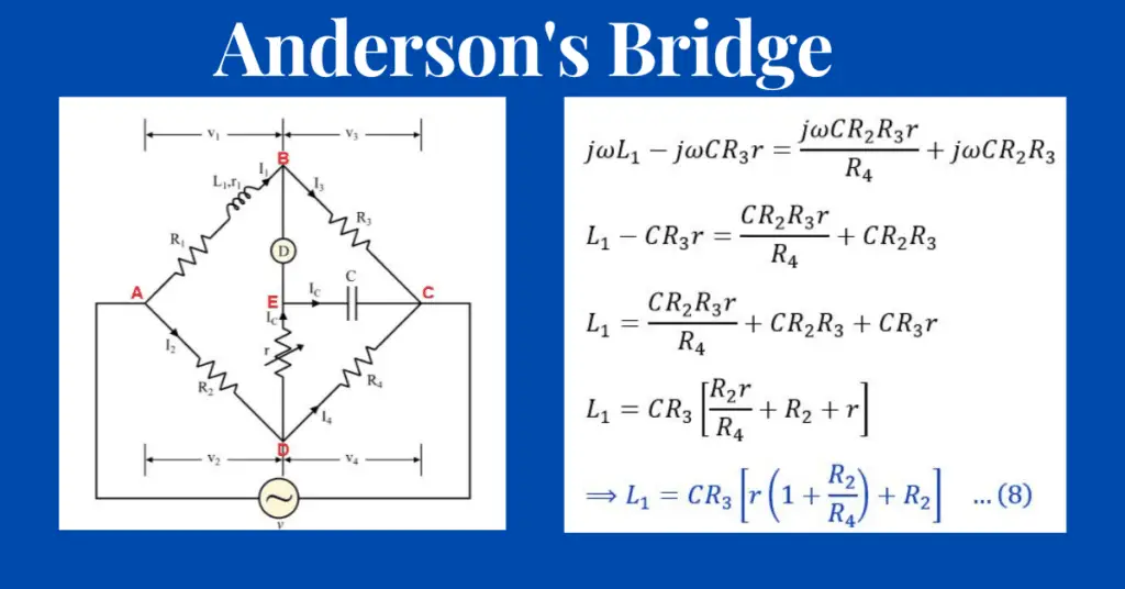
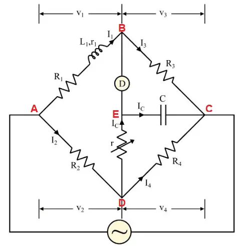
The circuit diagram of Anderson’s bridge is shown in Figure 1.
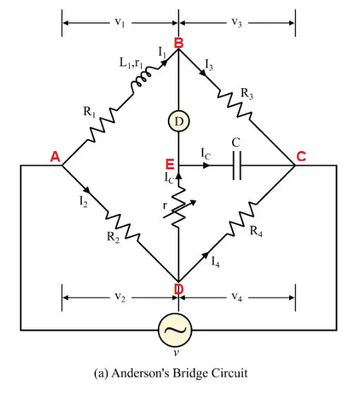
It consists of four arms namely ab, bc, cd, da. The circuit arrangement of Anderson’s bridge is as follows-
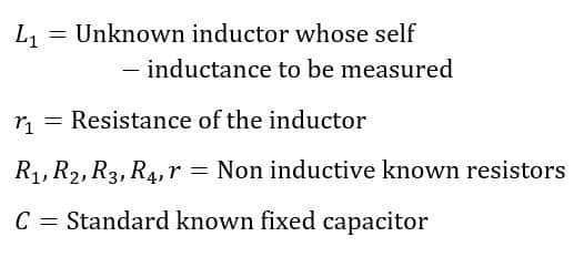
- An unknown inductance is connected between the terminals a and b along with a resistance R1 is connected in series with this unknown inductance.
- A fixed capacitor C is connected between the terminals c and e.
- A variable resistor r is connected between the terminals e and d.
- An alternating voltage source is connected between terminals a and c.
Equation of Anderson’s Bridge
In the circuit of Anderson’s Bridge, let,
At the balance condition of the bridge, we have,

And,
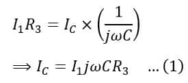
Now, the voltage across R and capacitor C is equal and no current flows through the galvanometer.
VBC = VCE
Therefore,
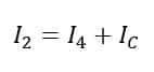
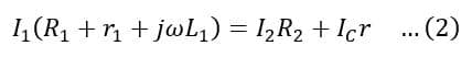
Another balance equations of the bridge are,
The voltage across AB = Voltage across AD + Voltage across DE
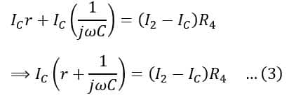
The voltage across VDE + voltage across VEC= Voltage across VDC
Now, on substituting the value of IC from equation(1) in equations (2) we get,
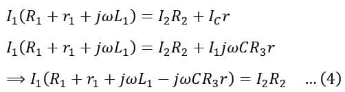
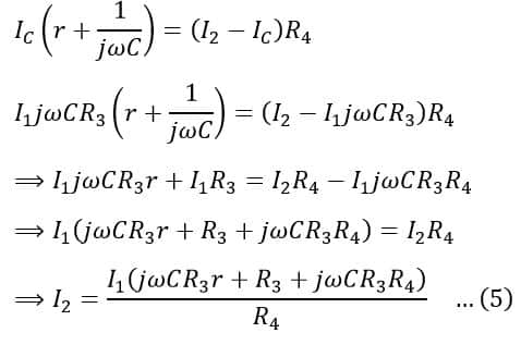
Now, on substituting the value of IC from equation(1) in equations (3) we get,
On substituting the value of I2 from equation(5) in equation (4), we get,
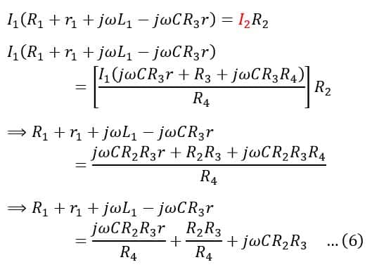
On separating the real and imaginary parts of equation (6), we get,
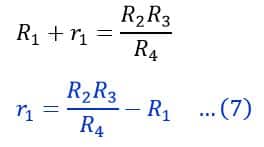
And,
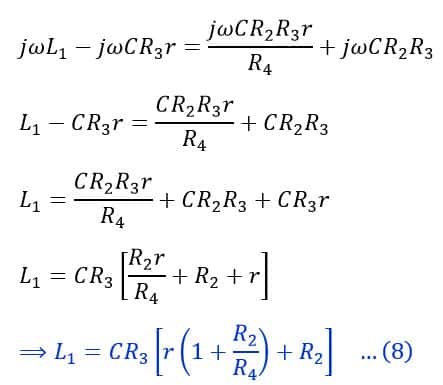
Hence, using equation (8), we can determine the value of the self-inductance of the coil.
Phasor Diagram of Anderson’s Bridge
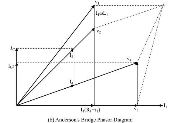
The current I1 is flowing through arm AB i.e., through non-inductive resistance R1 and inductor L1. Thus the total drop V1 in arm AB is the vector sum of I1 (R1 + r1) (which is in phase with I1) and I1 ωL1 (which is 90 degrees lagging with I1).
The same current will also pass through R3 (in arm BC) i.e., I1 = I3 when the bridge is balanced. Therefore, the voltage drop I3 R3 ( V3) is in phase with current I1. The potential between junctions BC will be equal to the potential between junctions EC because no current flow through the galvanometer under bridge-balanced conditions. Therefore, the voltage drop V3 = Ic/ωC and the voltage drop Ic r in the resistor r will lie along with Ic.
Voltage V4 will be equal to VEC when the potential across the galvanometer is zero under bridge-balanced conditions. Thus, V4 is the sum of the voltage drop across resistor r, and VEC. Thus, voltage V4 is the sum of voltage drop Ic r and V3.
The current I2 is the sum of the currents Ic and I4 under bridge balanced conditions. Therefore, the drop V2 ( I2 R2) in the arm AD due to I2 lies along with it. Therefore, the
The current I2 is the sum of the currents Ic and I4 under bridge balanced conditions. Therefore, the drop V2 ( I2 R2) in the arm AD due to I2 lies along with it. Therefore, supply voltage V is the resultant of the phasors V1 and V3 or V2 and V4.
Advantages of Anderson’s Bridge
The following are the major advantages of Anderson’s bridge-
- Anderson’s bridge determines the value of self-inductance more accurately.
- Anderson’s bridges require a standard fixed capacitor instead of a variable capacitor.
- In Anderson’s bridge, the bridge balance point can be easily obtained.
- A fixed capacitor is used in place of a variable capacitor in Anderson’s bridge. Hence, the bridge is cheaper than Maxwell’s bridge.
- It is possible to determine the value of unknown capacitance in terms of known inductance.
- The calculation of self-inductance of the coil does not get affected even with the use of an imperfect capacitor. The imperfect capacitor only affects the value of coil resistance.
- We need to subtract the lead wire inductance from the calculated inductance value for more precise measurements. Therefore, we can get the second balance condition by short-circuiting the coil, as a result, the bridge shows the value of leads inductance. The difference in both measurements of self-inductance shows the exact value of the self-inductance of a coil.
Disadvantages of Anderson’s Bridge
The following are the disadvantages of Anderson’s bridge-
- Anderson’s bridge involves a more complex process for determining the inductance equation.
- The provision of the capacitor junction in the bridge increases the circuit complexity, which in turn makes the shielding of the bridge difficult.
- The calculation of the bridge balance equation is more complicated than the calculation of Maxwell’s bridge.
Solved Problem on Anderson’s Bridge
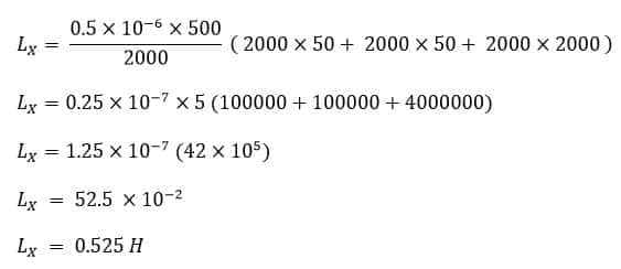
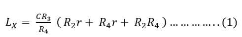
The above figure shows the connection of an Anderson Bridge for measuring the inductance Lx and Resistance Rx of the coil. Find Lx, if balance is obtain when R4 = R2 = 2kΩ, R3 = 500 Ω, r = 50 Ω and C = 0 .5 μF.
Solution:
At balance condition
As per the given values we have,
R4 = R2 = 2kΩ
R3 = 500 Ω
r = 50 Ω
C = 0 .5 μF
From equation 1,