A strain gauge load cell is a transducer that measures force and converts it into an electrical signal. In this post, we will discuss the construction & working principle of strain gauge load cells.
Working Principle
The elastic element when subjected to stress tends to change its dimensions. The steel cylinder when experiences a force, changes its dimension.
Now the question arises on how to convert this dimension change into an electrical signal. The strain gauge has four resistances connected in the Wheatstone bridge configuration. On conversion of the resistance of strain gauge into an electrical signal, it is possible to measure the dimension changes of the steel cylinder.
Now, what to do about this arrangement? If we bond the strain gauges on the steel cylinder, the change in the dimension of the cylinder will cause the strain gauge to change its dimensions. And, with a change in the dimension ( length and diameter) of the strain gauge, its resistance changes.
We can convert the change in the resistance of the strain gauge into an electrical signal.
Construction
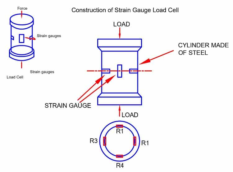
The main parts of strain gauge load cell are ;
- Steel cylinder
- Strain Gauges
The steel cylinder has four identical strain gauges. Out of 4 strain gauges, two strain gauges (R1 & R3) have their mounting along the direction of the applied load.
The other two strain gauges (R2 and R4 Horizontal gauges) are mounted on the circumference of the cylinder at right angles to gauges R1 and R3.
How does a load cell work?
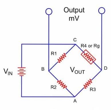
The output of the Wheatstone bridge circuit changes because of the change in the resistance on the application of load on strain gauge load cell. The output of the bridge circuit is in the order of millivolt or volt per input voltage.
Read More: What is a single-point load cell? its Working Principle
A thermal compensation circuit provides measurement accuracy. The thermal compensation is a must because the value of the resistances also changes with a change in the resistance.
We apply the input voltage between points B and C. This input voltage is the excitation voltage of the strain gauge load cell bridge. We obtain the output voltage across points B and D.
When there is no load on the load cell, there will be no deformation in the size of the strain gauges. It further leads to no change in the resistance value of the bridge. Under this condition, the bridge circuit is in balance, and the output voltage of the load cell is zero.
When there is the load on the gauge load cell. The resistance of the strain gauge R4 changes & the other three resistance value is unchanged. This condition causes unbalancing in the bride circuit and there will be voltage at output terminals.
The load cell bridge can have one, two, or four strain gauges. The output voltage is equal to the potential difference between voltage drop across R1 and R2.
VOUT =VCD – VCB
Applications
- Measurement of unsteady load
- Widely used in weigh bridges, weigh bins and weigh feeders.
Read Next :