Power Electronics, as the name says is the application of electronics in the field of high-power applications. Normally, Electronics whether Analog or Digital deal with low-power applications confined to a small DC voltage and current. These applications are known to be efficient and reliable. Power electronics came to the fore to bring the same efficiency and reliability to the field of high-power engineering.
Power Electronics is required in various fields like green and clean power systems, household electronic applications, Space technology, efficient motor drive control, etc. Precise control, efficiency, and reliability make power electronics a popular field.
Power electronics includes knowledge and working of semiconductors, electrical system models, control systems, actuators, etc. All these provide precise and complete control of an application.
Model of a Power Electronics-based system
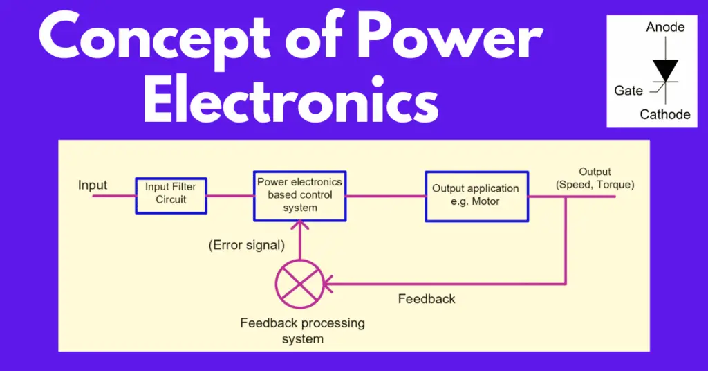
A general model of a power electronics-based system can be understood by the following diagram.
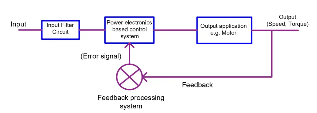
The model diagram is almost similar for all the power electronics-based control applications. Here we have taken an example of a motor application using a power electronics-based control system.
The input provided is the electrical power which then goes through a filter circuit where the voltage and current of the input are lowered to an appropriate value. This is then fed to a power electronic circuit which provides the appropriate and controlled input for the motor. The motor starts running which means it produces mechanical power calculated using torque and speed.
If the output torque or speed is not appropriate, a feedback path is provided which sends the output back to the power electronic-based control system. Based on this feedback, the controller generates an output that is fed to the motor for its appropriate and corrected functioning. We will understand the practical application of a power electronic-based control system in a while.
Scope of Power Electronics
Power electronics systems are known for their reliability and precise controllability. That’s why the scope of power electronics is huge. Whether it be Power Systems, Electrical Machines, Signal Processing, or Industrial applications, the role of power electronics is immense.
Power electronics revolutionized the way electrical systems worked and were controlled. One of the major issues that the power electronic-based systems addressed was improved efficiency with higher accuracy in the output of the applications. Earlier, we used to achieve one by sacrificing the other but power electronics changed the situation.
Let’s understand the working of a power electronics-based system.
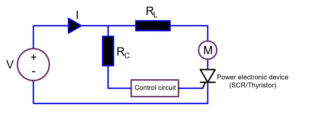
Power electronic-based control is achieved using elements called power electronic devices also known as switches. These devices are like SCR (Silicon Controlled Rectifier), MOSFET, BJT, GTO, etc. which help in fast switching and reliable control. Let’s understand the application of one i.e, SCR using the above diagram.
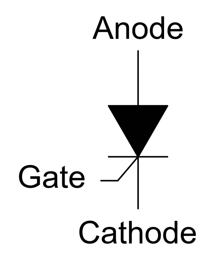
The circuit diagram shown above is that of a motor control system using SCR. SCR stands for Silicon Controlled Rectifier and is also known as Thyristor. It has three terminals – Anode, Cathode and Gate. It is similar to that of a diode except that it has an extra terminal called Gate.
Just like a Diode, an SCR is forward-biased when the Anode is connected to the positive terminal and the cathode is connected to the negative terminal of a voltage source. However, it can’t conduct unless the gate terminal is supplied with a voltage source. Once the gate terminal is active, the switch (SCR) behaves ideally like a short circuit and allows the normal flow of electric current.
Thus, the gate terminal acts like a control terminal for the switching device i.e, the SCR. If the gate terminal voltage is low, the switch acts as an open circuit and stops the current to flow whereas if the gate voltage is high, it allows the normal flow of current through the connected circuit. Thus, instead of cutting off the power source to the motor, we can turn the gate supply ON/OFF to start and stop the motor respectively.
Now, the question arises what is the use and advantage of this? What purpose does it serve?
The main advantage is controllability. Let’s say we need to reduce the speed of the motor. One method is to lower the voltage using a rheostat by dropping the voltage. But in that case, there is an immense loss of electrical power in the form of heat.
But with SCR, the gate terminal is supplied using a control circuit that generates electrical pulses of a specific duration as per the requirement. Pulses are DC voltages that go high for a specific amount of time and then go low. Such a type of pulse can be generated by a microprocessor which is fed to the gate terminal of the SCR.
Thus, the SCR turns ON/OFF alternatively causing the electric current to pass through the motor circuit. This causes the average voltage across the motor to fall and the motor speed drops down. This allows a smooth control of the motor speed, especially where applications are sensitive.
In addition to that, it provides efficient speed control. Unlike in the case of resistance-based speed control where there was a loss of power due to the voltage drop across the rheostat, the power loss in SCR-controlled speed control is very low.
These are the advantages associated with power electronics-based controlling using power electronics devices.
Power Semiconductor Devices
The following power semiconductor devices are widely used in power electronics.
- Power Diodes- General purpose, high speed, and schottky diode
- Thyristors – TRIAC, IGCT, MCT, LASER, RCT, SITH, GATT, GTO, and SCR
- Transistors- SIT, IGBT, MOSFET
Types of Power Electronics Circuits
There are five types of power electronic circuits widely used for power conversion.
- Rectifiers – The rectifier converts AC into variable DC. The types of rectifiers are half-wave rectifiers, full-wave rectifiers, and controlled rectifiers.
- Choppers – They are a DC-DC converter and convert fixed DC to variable DC
- Inverters – The inverter converts DC into AC with variable voltage and variable frequency
- Voltage Regulators – It converts fixed AC to variable AC at the same input frequency
- cyclo-converters – It converts fixed AC to AC with variable frequency
Advantages of Power Electronics Converters
Power electronics converters offer the following advantages.
- Highly reliable
- Small size and compact
- Consumes very less power
- Highly Efficient
- Very fast response
- Long Life
Disadvantages of Power Electronics Converters
The followings are the disadvantages of power electronics converter.
- Overload capacity limitation
- Generates harmonics
- Expensive
A Practical application of power electronics-based control
Let’s discuss a practical application of power electronics in our daily life: Working of an inverter-based Air-conditioning system.
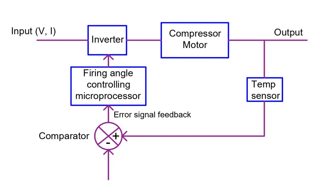
The above-shown model is that of a remote-controlled Air-Conditioning system. The input is provided from a power source having voltage V and a current I flows through the circuit. This is fed to the inverter which is the power electronics-based controlling device.
An inverter first converts the input AC voltage to DC. Finally, this DC voltage is switched using power electronic devices in such a way that it converts into controlled AC voltage. The frequency of the switching of the devices is based on the firing angle which is nothing but the time gap between two successive gate terminal pulses as the power electronic device allows conduction only when there is a gate pulse.
In an inverter, there are six such devices (e.g, MOSFET or IGBT) that turn ON and OFF in a pre-determined sequence such that the output voltage is alternating in nature. Therefore, the higher the pulses at the gate terminal of the respective power electronic device, the higher will be the switching rate and thus higher will be the average voltage that is applied at the compressor motor.
This causes the motor to start running. Because of the compressor, the room begins to cool down. Now, we make use of the remote control to set a temperature at which we want the AC to work. This has been shown by the “Reference Temp.” in the model diagram.
A temperature sensor senses the room temperature and feeds the data to a comparator. The comparator compares the room temperature data with the reference temperature (one set by the remote control) and finds the difference. This difference is known as an error signal which is fed back to the firing angle controlling microprocessor.
This microprocessor then generates the firing angle as required to minimize or neutralize the error. Let’s say the room temperature is 30 deg C and we want it to be 25 deg C. So, in this case, the reference temperature set by the remote control is 25 deg C. The comparator compares both temperatures and finds an error of 5 deg C. This is fed in the form of an electrical signal to the microprocessor which controls the firing angle of the power-electronic devices within the inverter.
As there is a gap of 5 deg C, the microprocessor generates more firing pulses with respect to time. This causes the power electronic devices to remain ON for longer instant of time and as a result, the average voltage at the compressor terminal increases. This causes the compressor to run faster and thus the room temperature goes down to minimize the error to zero.
Once the error goes to zero, the microprocessor slows down the number of pulses and therefore the average voltage to the compressor goes down as well. In this way, smooth, quick, and efficient control of the compressor motor is achieved with the help of a power electronics-based control system.
Other Application Areas of Power Electronics
In power system stability and control, power electronics play an important role. For example, the static VAR compensation to improve the transmission power factor and stability is controlled using power electronic devices.
In HVDC transmission, power converters are used which convert AC to DC on the sending end side while from DC to AC on the receiving end. It is one of the most efficient ways of bulk power transmission. The other application areas are as follows.
- Renewable energy: Used for conversion of dc power into AC power. The grid-connected renewable energy system offers various advantages and the power converters are used as a converter and inverters.
- Industries: In applications such as furnaces, welding, pumps and compressors, lighting, electroplating, induction heating, boiler, conveyors, elevators, lifts, cranes, electromagnets, electric vehicles, and furnaces, etc.
- Medical: Medical instruments and machines, such as MRI. X-rays etc.,
- Home Applications: Home appliances like Refrigerators, vacuum cleaners, washing machines, sewing machines, dryers, mixers and grinders, air conditioning, etc.
- Commercial Installations: In offices and commercial buildings power electronics applications comprise computers, electric fans, vending machines, audio amplifiers, battery charges, photocopiers, etc.
- Automotive and Security systems: CCTV, Electric vehicles, regulators, Radar/Sonar, Alarms, etc.
- Aviation and Aerospace: Satellite systems, aircraft and space vehicles, spaceship power systems, etc.
- Transportation: Motor drives, trains, trollies and subways, locomotives, streetcars, traction systems, elevators, magnetic levitation, etc.
- Telecommunication: UPS, DC power supply, radio and TV transmitter and receiver, wireless communication, etc.
- Power systems: Static circuit breakers, thyristor-controlled reactors, energy storage systems, harmonics suppression, etc.
- Digital Signal Processing- Digital to analog and analog to digital conversion