The core of the transformer is the main part of a transformer and it carries the magnetic flux. Electrical Transformers are one of the most important electrical machines of all time. These have a wide variety of applications. Generally, these transformers are used to transfer AC electrical power from one part of the circuit to another at an elevated voltage or current.
Like in the case of power transformers or generator transformers, the generated voltage from the power station is fed to these transformers which boost the voltage (and thereby reduce the current as transformers keep input and output power constant assuming losses to be negligible) and sends it over the transmission line. The advantage of higher voltage is that the required transmission line is thinner and there are no such problems as excessive heat loss or voltage drop. Also, the power factor remains good.
Similarly, transformers are used to step down voltage or current in order to measure them accurately and safely using low or medium-range measuring devices. These transformers are called instrument transformers. A variety of them is used for actuating relays in case of any fault.
Thus, we can keep on talking endlessly about the importance of transformers in various applications and thus it is important to understand how these transformers work. For that, we have to understand the design of a transformer. The two most important design aspects of an electrical transformer are – The core and the winding. Today we are going to talk about the core design and its overall importance not only in transformers but in any choke coil inductor.
Importance of core of Transformer
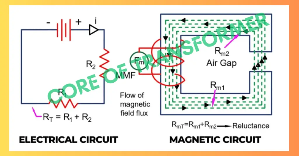
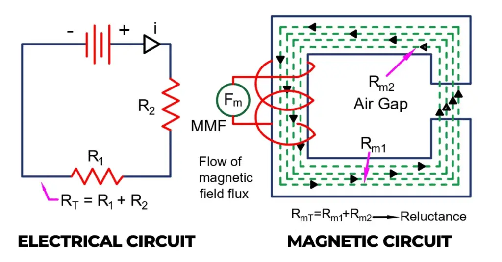
For electrical current to flow through a circuit, we need to have a battery or any other EMF source connected to it. The circuit is formed from a conducting material that allows the current to flow and offers a certain amount of resistance to it. This is what we call an electrical circuit.
Analogous to that, we have a magnetic circuit. The Magneto-motive Force (MMF) is similar to that of EMF or battery source in an electrical circuit and it allows the magnetic field flux to flow through the magnetic circuit made by the core material. Here, the magnetic field flux is analogous to the electrical current while the core material is similar to that of a conductor in an electrical circuit. The core material offers a physical quantity called Reluctance which is analogous to resistance or impedance in an electrical circuit. Reluctance restricts the flow of magnetic field flux through the core.
Design of a core material of Transformer
From the analogous comparison done above, it is clear that core material is one of the most important components of not only in transformers but in any inductor-based circuit. Just like in the case of an electrical conductor, we want the material to have high electrical conductivity and low resistance, in the case of magnetic core material we want it to have high permeability and low reluctance. For that, we have to focus on its design aspects.
Core material, therefore, must be made using materials that are ferromagnetic i.e, the ones which have great magnetic properties so that they can carry the magnetic field flux efficiently without causing it to leak out and get linked with nearby materials.
There are several key aspects for designing the core of a transformer. These are:-
Core Material
The core material must have a high magnetic permeability to allow the magnetic flux to flow easily through it, as well as a low coercivity to prevent hysteresis losses. Common core materials include silicon steel, nickel-iron alloy, and ferrite.
Core Shape
The shape of the core affects the magnetic path and the amount of flux leakage. Common core shapes include rectangular, circular, and toroidal.
Core Size
The size of the core is determined by the required cross-sectional area to accommodate the magnetic flux density and the number of turns of the windings.
Winding Configuration
The winding configuration affects the distribution of the magnetic flux in the core and the amount of electromagnetic interference (EMI) generated by the transformer. Common winding configurations include single-phase and three-phase windings.
Core Stacking
The number of cores used to build the transformer affects the amount of magnetic flux leakage, the size of the transformer, and the mechanical stability of the core.
Core Laminations
The core is typically made up of laminations to reduce eddy current losses and improve efficiency. The thickness of the laminations and the insulation between them affect the magnetic permeability and the eddy current losses.
Core Jointing
The joints between the core laminations affect the magnetic path and the amount of flux leakage. Common jointing methods include overlapping, butt-jointing, and step-lapping.
Core Coating
Coating the core with an insulating material can reduce eddy current losses and improve efficiency.
Eddy current and Hysteresis loss in the core of the transformer
Eddy current and Hysteresis losses are known as core losses as these are magnetization losses in an AC machine. The core of a transformer must be designed in a way so that these losses could be made as small as possible.
Eddy currents are created when a magnetic field flux links with the core material and causes an EMF to generate hence causing a current to flow through the core material. The core of a transformer is for carrying the magnetic field flux and not carrying current. This is a loss as a part of the input electrical power is being wasted in the form of eddy current as a part of the useful magnetic field flux links with the core. These eddy currents lead to energy losses in the form of heat, which can cause inefficiencies in the transformer.
To reduce the eddy current loss, the core of the transformer can be constructed from thin sheets or laminations of steel which are insulated from each other. This reduces the amount of metal in the core and thus reduces the eddy currents.
In addition to that, the core material can be chosen to have a high resistivity, which reduces the amount of current that can flow through the core and thus reduces eddy current losses. Some common core materials used for this purpose are silicon steel and amorphous metal.
Hysteresis losses are a form of energy loss in a transformer caused by the magnetic hysteresis of the core material. When the magnetic field in the core is repeatedly reversed due to the alternating current in the windings, energy is lost as heat due to the hysteresis effect. It is represented by the following B-H curve.
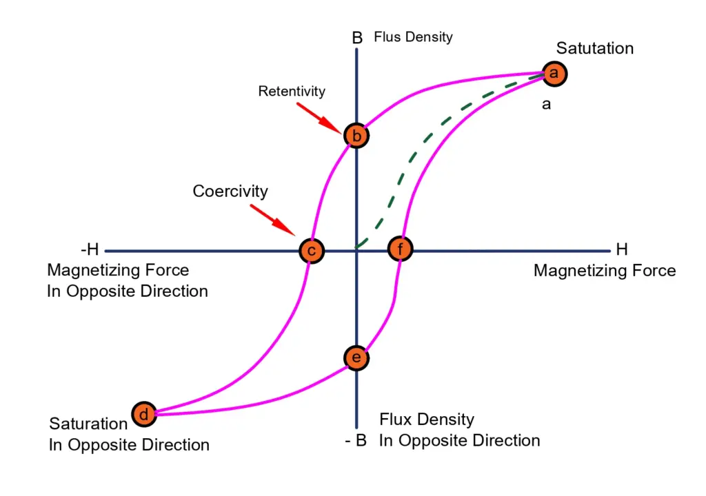
Choosing a core material with low coercivity and low hysteresis loss can significantly reduce the energy loss due to hysteresis. Materials such as silicon steel, which have a low coercivity and low hysteresis loss, are commonly used for this purpose.
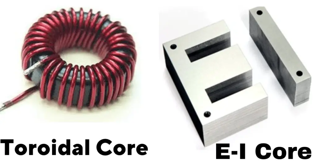
The shape and size of the core can also affect the hysteresis loss. A toroidal (donut-shaped) core, for example, can reduce hysteresis losses compared to a rectangular or E-I-shaped core due to the absence of corners, which can result in concentrated magnetic flux. However, the selection of the core also depends on the type of application. Toroidal core is usually used for low-power electronic applications whereas E-I core is required in medium to high-power applications.
Types of the core design of Transformer
There are two types of core designs that are used in a transformer – Core type and Shell type.
Core Type
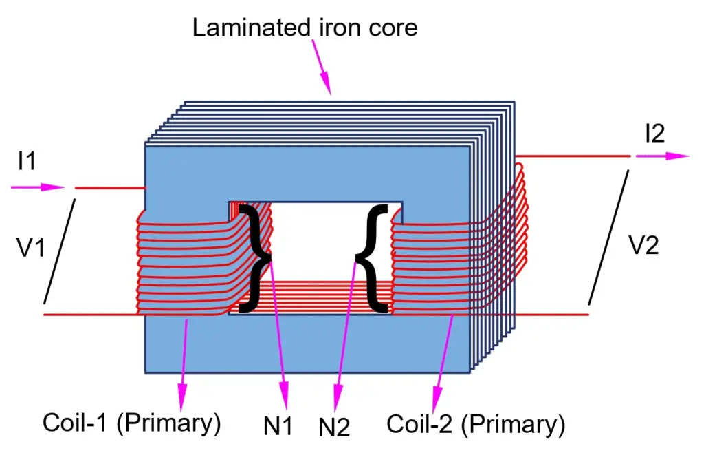
In a core-type transformer, the windings are wound around one leg of a laminated E-I-shaped magnetic core, and the other leg completes the magnetic circuit. The shape of the core resembles the letter ‘I’ or ‘E’, hence the name.
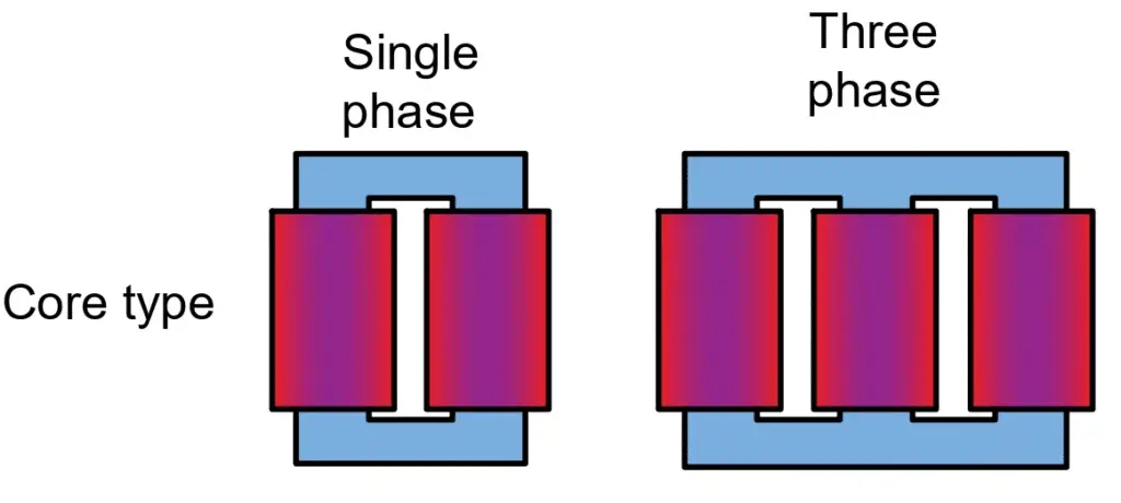
This configuration offers good magnetic coupling between the primary and secondary windings and is commonly used in high-voltage and power transformers.
Shell Type
In a shell-type transformer, the core surrounds the windings like a cylindrical shell, and the windings are wound in concentric circles around the core. The shape of the core resembles a cylindrical shell, hence the name.
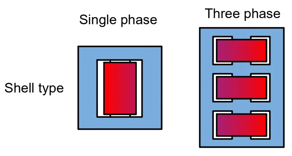
This configuration is often used in low voltage and small power transformers, where the flux density is relatively low and magnetic leakage is not a significant concern.
Advantages & Disadvantages of Core and Shell type Transformer cores
Both core type and shell type configurations have their own advantages and disadvantages.
- Core-type transformers have better magnetic coupling between the primary and secondary windings, resulting in higher efficiency and better regulation.
- However, they can be more expensive to manufacture and are not suitable for applications that require high leakage inductance.
- Shell-type transformers, on the other hand, are less expensive to manufacture and can be used in applications where high leakage inductance is desired.
- However, they may have lower efficiency and poorer regulation than core-type transformers.
The choice between core type and shell type configuration depends on the specific requirements of the transformer application, such as voltage and power rating, efficiency, and cost.