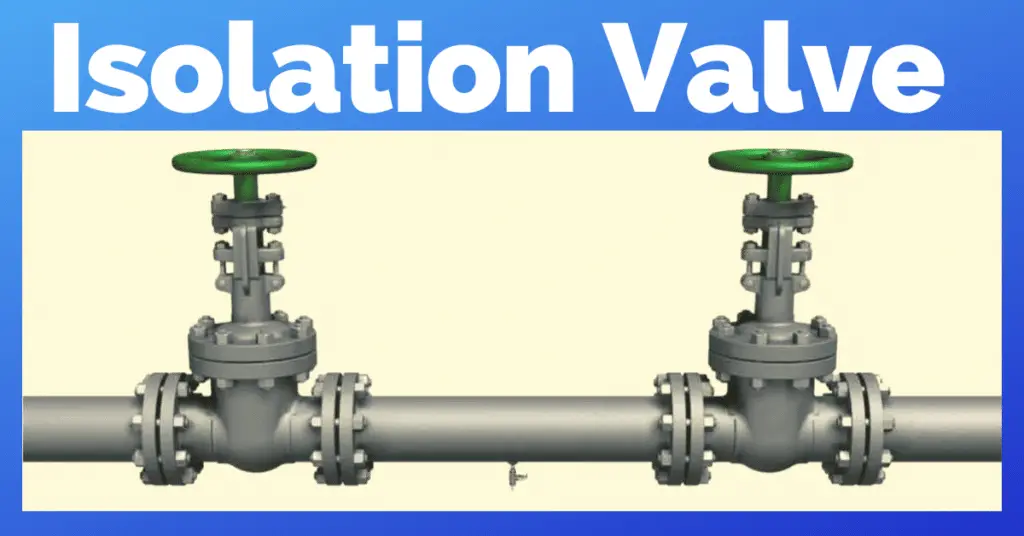
The isolation valves in an industrial process plant are an integral part of the safety system. Process isolation is achieved in various ways that include an emergency shutdown, double block- and bleed, or simple manual block valve.
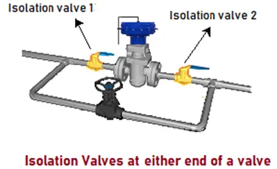
The first step in preparing for the maintenance of any fluid system is depressurization. To prevent pressure buildup in the section of the line under maintenance, it is best to have two shutoff valves in sequence.
The seat of a good valve should not leak, but there is a possibility that it can. There are other possibilities, such as the valve being improperly maintained or not being able to close consistently.
Purpose of Isolation
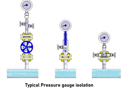
During the maintenance of industrial fluid systems, safety is paramount. A contained pressure or flow from a single line poses a risk to technicians who are replacing a pressure gauge, pressure transmitter, or another measuring device.
For this reason, there is a necessity to isolate a process line in the system before proceeding with maintenance.
Principle locations of Isolation configuration
For any fluid system line in an industrial facility that needs maintenance, technicians must have several ways available to safely isolate the line.
Some specific locations that require an isolation configuration are;
- Instruments that require periodic maintenance such as pressure gauge, transmitter, filter, or valve.
- Any line or system that may need to be repaired, reconfigured, or replaced.
- Any section of the main process piping that may require maintenance or repair.
- The calibration fluids in sampling systems, as well as any sample streams, must need be switched.
How to create Process Isolation
Designing and installing two shutoff valves in sequence to bleed off a pressurized section of a fluid system has become a safety and industry standard. The double shut-off valve sequence is one of the safest ways to get to zero pressure, a zero flow must-have situation.
- To isolate fluid systems, engineers use two common methods in designing double-seal valve configurations.
- The first is to add a third valve between the two shutoff valves to vent or bleed off any pressure that may leak from the first shutoff valve.
As shown in the figure below, another possible option is that the third valve diverts the flow to a bypass loop that returns to the section of the line under maintenance.
Both configurations of fluid systems are described below, with design approaches oriented towards safety in isolation and maintenance.
Isolation Configurations
An industry standard is to avoid situations where there is only one shutoff valve or no backup valve. In the event the shutoff valve has a small leak, pressure can slowly build up in the line under maintenance, creating a safety hazard.
Therefore, it is recommended to use one of the two main configurations to carry out the isolation of a fluid line.
- Double Block ad Bleed configuration
- Bypass loop
Double Block and Bleed or vent (DBB)
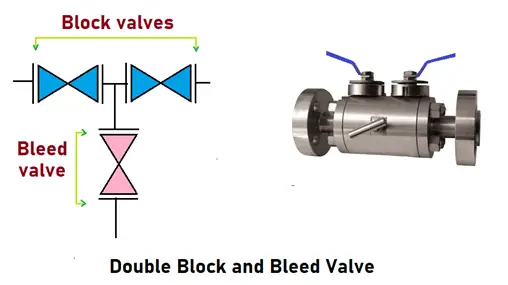
A double block and bleed or vent (DBB) configuration is the simplest configuration for isolating a fluid system. They are typically used as a transition between the process line and an instrumentation line when using a process interface valve or in a line leading to an instrument or device such as a transmitter.
All three valves can be configured as a single manifold or as three separate components.
Bypass loop
A bypass loop configuration is somewhat more complicated, that not only isolated the line from the fluid system under maintenance but redirects flow to allow the process to continue.
For example, in the bypass configuration, the first shut-off valve might be a two-way or a three-way valve. It directs flow by bypassing it to the section under maintenance. Then the system filter can be changed without stopping it. Another reason that justifies the bypass is to avoid hydraulic shock or water hammer that results from a sudden shutdown of system flow.
Types of Isolation valves
The two most common options for shutoff valves for process isolation in instrumentation lines are ball and needle. But a better choice is to use a double-shut-off and bleed valve. It is a device consisting of two isolation valves separated by a bleeder. The service technician needs to check up the system specifications for which valve each system requires.
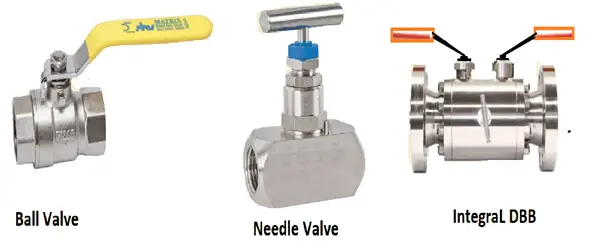
Ball Valves
The ball valves are well suited to high-flow and quick closing. Another advantage is that the control help to see the direction of the flow and indicate if they are closed. In liquid flows, however, a ball valve can cause hydraulic shock or a “water hammer” if its operation is the suddenness of opening and closure.
A sudden operation to open causes damage to pressure gauges, transmitters, flow meters, and other components upstream of the closure.
The second choice is to use needle valves instead of ball valves.
Needle Valves
Although needle valves are designed to control or regulate flow, many of them are efficient in closing consistently. In addition, the closure of a fluid system with a needle valve is gradual, thus avoiding hydraulic shocks. If it is to be used as a shut-off valve, the needle valve should be designed for that particular purpose, with a ball or soft-seal plug.
Integral DBB
Integral Double Block and Bleed (DBB) configuration avoid potential leaks, can accommodate less space, weight, and easy installation all of these will help to simplify the system. It is a good habit to install a pressure gauge downstream of the second stop valve in the isolation configuration. This will allow you to visually check the pressure during maintenance.
Paying attention to properly isolating our fluid system lines with isolation valves is not only safer for carrying out maintenance but also increases uptime and plant throughput.