Electric current is the ratio of charge transferred in a given period. In other words, the rate of transfer of electric charge is the electric current. If the one-coulomb charge is transferred in one second from one point to another, the circuit carries the one-unit current.
In this article, we will explain the symbol of electric current, the formula of current and the different types of electric current such as AC (Alternating Current) and DC (Direct Current). We will also cover how current flows in a circuit, its unit of measurement, and practical examples for better understanding.
What is an Electric Current?
Electric current is the flow of electric charge through a conductor or circuit. For electric current to flow, there must be a potential difference (voltage) between two points in the circuit.
This potential difference acts like pressure, pushing the charged particles—usually electrons—to move from one point to another. The movement of these charges constitutes the electric current.
Symbol of Electric Current
The standard symbol of electric current is represented by the letter I. This notation comes from the French word intensité du courant (meaning “intensity of current”). Apart from the letter I, electrical drawings use special graphical symbols to represent the two main types of current:
In circuit diagrams, current is usually shown by an arrow (→) indicating the conventional direction of current flow (from positive to negative terminal of voltage source).
DC Current Symbol
The symbol for direct current is usually denoted by a straight line (—) above a dashed line (···).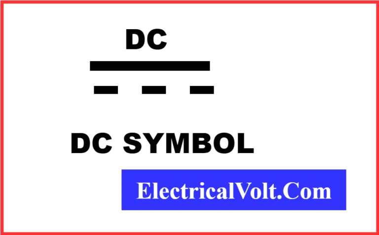
AC Current Symbol
The symbol for alternating current is a wavy line (~).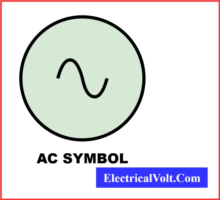
Formula for Electric Current
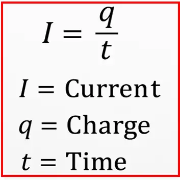
The basic formula of electric current is:
I= q/t
where:
- I= electric current (in amperes, A)
- q = total electric charge (in coulombs, C)
- t= time interval over which the charge flows (in seconds, s)
Example
If a 500 Coulomb charge passes through a conductor in 100 seconds, then the current is:
I = 500 / 100 = 5 Ampere
Differential Form of Electric Current Formula
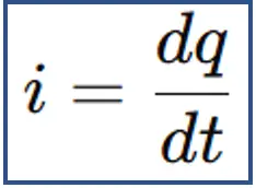
However, when the electric charge varies continuously with time, it is more accurate to express the current in its differential form:
I= dq / dt
Where:
- I = instantaneous current (in amperes, A)
- q = electric charge (in coulombs, C)
- t = time (in seconds, s)
- dQ/dt = derivative of charge with respect to time, representing how fast the charge changes at that instant
This differential form is particularly useful in AC circuits, transient analysis, and physics problems, where current is not constant but changes over time.
Example:
If q(t)=5t2 coulombs, then:
i(t)=dq/dt=10t A
At t=2 seconds:
i(2)=10×2=20 A
Thus, the differential form allows precise calculation of current at any instant.
Formula for Electric Current in Terms of Voltage
According to Ohm’s Law: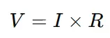
Rearranging for current: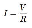
Where:
- I= electric current (in amperes, A)
- V = potential difference or voltage across the conductor (in volts, V)
- R = electrical resistance of the conductor (in ohms, Ω)
Example: If a resistor of 10 Ω is connected across a 20 V battery, the current is:
I=V/R=20/10=2A
SI Unit of Electric Current
Since electric charge and time are fundamental physical quantities with units of coulomb (C) and second (s) respectively, the unit of electric current is expressed as coulomb per second (C/s).
This unit is termed the ampere (A), named after the French scientist André-Marie Ampère, who made pioneering contributions to the study of electrodynamics.
In the SI system, the standard unit of electric current is the ampere (A).
In the CGS system, the unit of current is the biot (or abampere), and 1 biot is equivalent to 10 amperes.
By definition, if 6.241 × 10¹⁸ electrons move through a conductor in one second, the resulting current is one ampere.
The ampere (A) serves as the universally accepted unit of current in electrical and electronic applications.
For smaller magnitudes of current, the following sub-units are commonly used:
- 1 milliampere (mA) = 10⁻³ A
- 1 microampere (µA) = 10⁻⁶ A
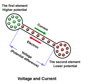
How Does Electric Current Flow in a Circuit?
The electric current flows from the higher potential to the lower potential. If the two points in the circuit are at the same potential, the flow of electric charge is zero; hence, the current is zero.
The magnitude of the current depends on the rate of flow of charge from one point to another in a given circuit. The higher the rate of flow of charge, the higher the current.

In metal, free electrons, which move randomly within the metal, are abundantly available.
When we connect metal to a supply source, the source electron repels the electrons of the metal towards the higher potential of the supply source, and thus, the positive point of the supply source at the higher potential attracts the drifted electrons.
This way, the flow of electrons causes the current to flow.
Initially, people assumed that electric current flows due to positive charges. Experiments have shown that the main reason for current flow is the drift of electrons from lower to higher potential. The flow of current caused by the external field is the drift current.
The direction of electric current is opposite to that of electrons. The conventional direction of the current is from the higher to the lower potential point. This is why circuit diagrams often show arrows pointing in the opposite direction of actual electron movement.
In simple terms, electrons (negative charges) move from the negative terminal to the positive terminal of a power source, while conventional current flows from positive to negative.
Example- Flow of Electric Current & Its Direction in a Circuit
In a torch with a battery, when you switch it on, electrons flow through the filament of the bulb from the battery’s negative terminal to the positive terminal. However, Conventional current flows from the positive terminal of the battery, through the bulb, and returns to the negative terminal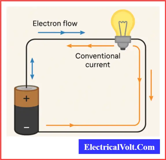
History of Electric Current Theory
The understanding of electricity developed over centuries:
- Benjamin Franklin (1706–1790): Introduced the concept of positive and negative charges and proposed the idea of electric “fluid.”
- André-Marie Ampère (1775–1836): Defined electric current and studied its magnetic effects.
- Michael Faraday (1791–1867): Discovered electromagnetic induction, showing how electricity can be generated.
- Georg Ohm (1789–1854): Formulated Ohm’s Law, relating voltage, current, and resistance.
- 1897 – J.J. Thomson: Discovered the electron, clarifying that electric current in metals is due to moving electrons.
- Conventional Current Definition: Before the discovery of the electron, scientists assumed that current flows from positive to negative—a convention that circuit diagrams still follow today.”
Basic Laws Governing Electricity
Several fundamental laws form the backbone of electric current theory:
- Ohm’s Law: States that the current through a conductor is directly proportional to the voltage across it and inversely proportional to its resistance: I=V/R (Read detailed article: Ohm’s Law — Definition, Formula, Examples)
- Kirchhoff’s Laws:
- Current Law (KCL): The sum of currents entering a junction equals the sum leaving it.
- Voltage Law (KVL): The sum of voltage drops around any closed loop is zero.
(Read detailed article: Kirchhoff’s Laws — Explanation and Applications)
Charge, Voltage, and Resistance Basics
Before understanding current types, it’s essential to know three core concepts:
- Electric Charge (Q): The physical property of matter that causes it to experience a force in an electric field. Measured in coulombs (C). (Read detailed article: Electric Charge– Definition, Types, Unit and Properties)
- Voltage (V): Also called potential difference, it represents the work required to move a unit charge from one point to another. Measured in volts (V).
- Resistance (R): The opposition offered by a material to the flow of current. Measured in ohms (Ω). (Read detailed article: Electrical Resistance-Definition, Formula, and its Unit)
These quantities are related through Ohm’s law and determine how electricity flows in a circuit.
Types of Electric Current
There are two types of electric current.
- Direct Current (DC)
- Alternating Current(AC)
Direct Current (DC)

Direct current (DC) refers to the flow of electric charge in a single, constant direction — making it unidirectional. In a DC circuit, electrons move from the negative terminal to the positive terminal of the voltage source.
However, by the conventional current definition, DC is said to flow from the positive terminal toward the negative terminal, since the current’s direction is taken opposite to the actual movement of electrons.
DC is commonly used in batteries, solar panels, and electronic devices because it provides a steady and constant voltage.
Alternating Current (AC)
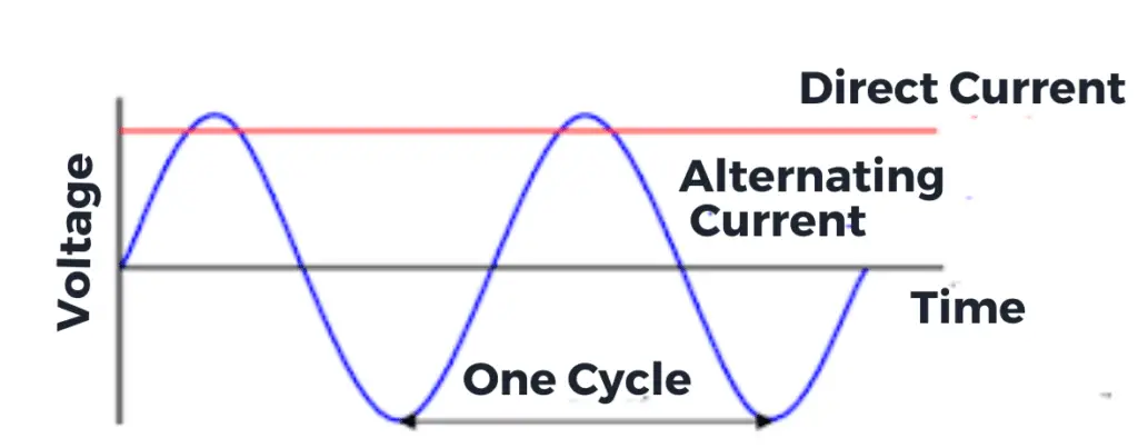
When the current flows in positive and negative directions alternatively in a cycle, it is called alternating or AC.
This type of current changes its direction and magnitude periodically, and its frequency is measured in hertz (Hz).
In most countries, household AC supply has a frequency of 50 Hz, meaning it changes direction 50 times per second. AC is used for transmitting electricity over long distances because it can be easily transformed to different voltages using transformers.
Measurement of Electric Current
The magnitude and direction of electric current are measured with the help of instruments like a galvanometer or an ammeter.
A galvanometer is a sensitive device equipped with a pointer that moves across a calibrated scale, indicating both the direction and strength of current flow.
An ammeter (short for Ampere-Meter) is specifically designed to measure the current in a circuit with higher accuracy.
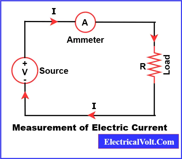
To measure current, the chosen instrument is always connected in series with the circuit, ensuring the entire current flows through it for a correct reading.
Conventional Current Flow vs Electron Flow
Conventional Current Flow
Conventional current flow is the assumed direction of current in a circuit. By this convention, current is taken to flow from the positive terminal of a power source toward the negative terminal. This idea originated before the discovery of electrons and their negative charge. Although electrons actually move in the opposite direction, this convention is still widely used in circuit diagrams and electrical calculations.
Electron Flow
Electron flow represents the true physical movement of charges in a conductor. Electrons, being negatively charged, travel from the negative terminal of a power supply toward the positive terminal. This is because they are repelled by the negative terminal and attracted to the positive terminal. Hence, electron flow is exactly opposite to conventional current flow.
Key Differences Between Conventional Current Flow and Electron Flow
| Aspect | Conventional Current Flow | Electron Flow |
| Description | Current is considered to move from the positive terminal to the negative terminal. | Electrons actually move from the negative terminal to the positive terminal. |
| Direction of Current | Assumes movement of positive charges. | Involves movement of negatively charged electrons. |
| Basis | Standard approach in electrical engineering and circuit analysis. | Explains the real behavior of charge carriers. |
| Charge Movement | Imaginary flow of positive charges in the direction of current. | Actual flow of electrons in the opposite direction. |
| Accuracy | A historical convention, not physically accurate. | Reflects the true motion of charges in a conductor. |
Effects of Electric Current
The flow of electric current in a conductor produces several noticeable effects. For instance, when current passes through a resistor, the resistor opposes the flow of charges. This opposition does not stop the current completely, but the electrical energy is transformed into heat energy, which is released as heat. This phenomenon is known as the heating effect of current.
In a similar way, electric current can also produce a magnetic effect and a chemical effect, depending on the type of conductor and the conditions under which the current flows.
Chemical Effect of Electric Current
When an electric current is passed through a conducting solution (electrolyte), it dissociates into its respective ions. These ions move toward the electrodes, where visible changes can be observed.
For example, the color of the solution may change due to ionic movement, gas bubbles may form at the electrodes as a result of chemical reactions, and in some cases, metal ions get deposited on the electrodes. These effects together are known as the chemical effect of electric current.
The chemical effect plays a vital role in many practical applications. It is the working principle behind electroplating, electrolysis, purification of metals, and batteries. In these processes, electric current drives chemical reactions that either produce new substances, deposit materials on surfaces, or separate elements from compounds, making it one of the most important effects of electricity in daily life and industry.
Heating Effect of Electric Current (Joule’s Law)
Electric current flows in a circuit when a voltage is applied across it. The magnitude of the current depends on the voltage V and circuit resistance R. As the current passes through a conductor, electrical energy is converted into heat energy due to the opposition offered by the conductor’s resistance.
The rate of heat produced in the circuit depends on the resistance and the square of the current.
H = I2 Rt
Where,
I = Current in ampere
R = Resistance in Ohms
t = Time in Seconds
This is known as Joule’s Law of heating. It states that the heat produced in a conductor is directly proportional to the square of the current, the resistance of the conductor, and the time for which the current flows.
Common applications of the heating effect of electric current include electric heaters, toasters, electric irons, water geysers, and filament bulbs. In these devices, materials with high resistance (such as nichrome) are used to produce heat efficiently.
Read detailed article on: Heating Effect of Electric Current- Definition, Examples and Applications
Magnetic Effect of Electric Current
A magnetic field is set up around the current-carrying conductor. The strength of this magnetic field increases with the magnitude of the current and decreases with distance from the conductor.
We can find the direction of the magnetic field using the right-hand rule. In this rule, if you hold the conductor with your right hand so that your thumb points in the direction of current flow, the curl of your fingers will indicate the circular path of the magnetic field lines.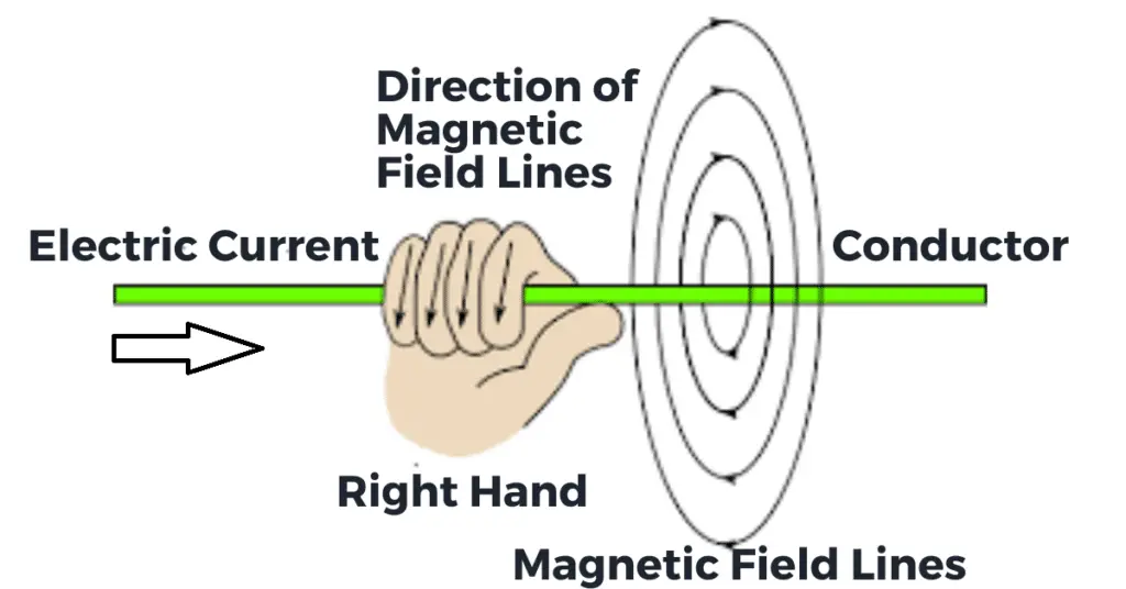
If a current-carrying conductor is placed in a magnetic field, the conductor experiences a force.
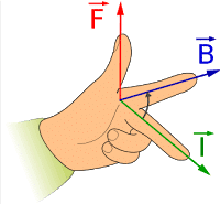
The magnitude of the force depends on the magnitude of the current through the conductor and on the strength of the magnetic field. The direction of the force can be found using Fleming’s left-hand rule.
This rule helps to determine the direction of the force acting on the conductor. Here, the forefinger represents the magnetic field, the middle finger represents the current, and the thumb represents the direction of the force.
Fleming’s Left Hand Rule. This interaction between current and magnetic field is the principle behind devices like electric motors, loudspeakers, and electromagnetic relays.
Applications of the Magnetic Effect of Electric Current include:
- Electric motors – convert electrical energy into mechanical rotation.
- Loudspeakers – use electromagnetic force to produce sound.
- Electromagnetic relays – control high-power circuits with low-power signals.
- Magnetic cranes – lift and move heavy metallic objects.
- Galvanometers – detect and measure small currents.
Formula for Force on a Current-Carrying Conductor
The magnitude of the force can be expressed as;
F= BILSinθ
Where:
- F = Force on the conductor (in Newtons)
- B = Magnetic flux density (in Tesla)
- I = Current flowing through the conductor (in Amperes)
- L = Length of the conductor within the magnetic field (in meters)
- θ = Angle between the conductor and the magnetic field lines
This equation shows that the force is directly proportional to the strength of the magnetic field, the current through the conductor, and the length of the conductor in the field. The term sin θ indicates that the force is maximum when the conductor is perpendicular to the magnetic field (θ = 90°) and zero when it is parallel (θ = 0°).
This principle forms the basis for the operation of electric motors, where current-carrying conductors are intentionally placed in magnetic fields to produce rotational motion.
Example:
If a conductor of length 0.5 m carries a current of 3 A through a magnetic field of 0.2 T, placed at a right angle (θ = 90°) to the field:
F= BILSinθ
=0.2×3×0.5×sin90∘
F=0.3 N
So, the conductor experiences a force of 0.3 Newtons.
Applications of Electric Current
Electric current plays a vital role in almost every aspect of modern life. Some common applications include:
- Electronics: Powers devices like computers, smartphones, and home appliances.
- Lighting: Supplies energy to incandescent bulbs, LED lights, and street lamps.
- Transportation: Runs electric trains, trams, and electric vehicles (EVs).
- Power Grids: Distributes electricity from power plants to homes and industries.
- Electroplating: Used in industries to coat metals for corrosion resistance or decorative purposes.
- Medical Equipment: Powers X-ray machines, ECG monitors, and other diagnostic devices.
Safety Precautions with Electric Current
While electric current is useful, improper handling can be dangerous. Essential safety measures include:
- Grounding: Ensures stray current flows safely into the ground.
- Fuses: Break the circuit in case of excess current flow to prevent overheating.
- Circuit Breakers: Automatically stop the current in case of faults or overloads.
- Insulation: Electrical Insulation prevents accidental contact with live wires.
⚠️ Always handle electrical devices with care and follow safety guidelines, especially in school or college laboratories.
Electric Current Theory – FAQs
The SI unit of electric current is the ampere (A), which represents one coulomb of charge passing through a point in one second.
The symbol of electric current is I.
The symbol for AC is a sine wave (~).
Electric current is given by: I = Q / t.
Current is measured in amperes (A), not volts.
AC (Alternating Current) changes direction periodically, while DC (Direct Current) flows in a single, constant direction.
Conventional current assumes current flows from the positive to the negative terminal, based on early scientific convention. However, electrons are negatively charged and actually flow from negative to positive.
Electric current is measured using an ammeter, which is connected in series with the circuit.
Related Articles:
do not copy the contents of http://www.electricalvolt.com
Yes you may link my website page URL in your post