The insulated bearing for the motor is used to prevent the circulating current through the motor bearing. The circulating bearing current can damage the bearing. When we run an induction motor with a variable frequency drive, it is apt to fail due to bearing failure. In this article, we will discuss how the circulating current flows through the motor bearing when VFD drives the induction motor. We will also discuss how to prevent the circulating current in order to prevent the bearing damage.
How do VFDs Cause Bearing Damage?
In large-rate motors and alternators, induced shaft voltage causes a flow of circulating current from the motor shaft to the outer race, rollers, or balls of the bearing. The circulating current can damage the bearing. That is why we ground the motor shaft through the carbon brush so that the circulating current finds its path to the ground and does not pass through the bearing. The same phenomenon happens with an induction motor driven by VFD. The magnitude of circulating bearing current with VFD is much higher, and it causes bearing damage.
VFD induced Shaft current in AC Motor
Let us understand how the shaft voltage is built up when PWM current flows through the motor winding.
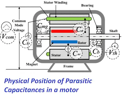
The motor has insulation and conductive parts, therefore capacitance is formed between the insulating and conductive parts of the motor. The parasitic capacitance formed between the various parts of the motor becomes more relevant when the motor is driven by a PWM voltage source inverter. The equivalent circuit of the motor, considering all the parasitic capacitance, is given below.
Parasitic capacitances in an induction motor
The various parasitic capacitances formed in the motor are termed as follows;
CSF – Stator to Frame Capacitance
CSR– Stator to Rotor Capacitance
CRF – Rotor to Frame Capacitance
CB – Bearing Capacitance
All the above capacitance is responsible for inducing the shaft voltage in an induction motor. The capacitance value is low when we run an induction motor with pure sinusoidal voltage. However, with VFD, the value of the parasitic capacitance is different, and it causes voltage across the motor shaft.
CSF – Stator to Frame Capacitance
This is the primary capacitance formed between the stator winding and the grounded frame of the motor. The value of capacitance is the largest among all parasitic capacitances. Most of the common mode current is caused by the high dv/dt of the common mode voltage of PWM waveforms that flow through this path.
CSR – Stator to Rotor Capacitance
This capacitance is formed between the stator winding and rotor frame. The value of the capacitance is rather small. Still, it has more significance in view of charging the shaft, which is physically connected to the rotor, and this parasitic capacitance is responsible for shaft voltage. Therefore, the value of this capacitance is very paramount for evaluating the magnitude of shaft voltage.
CRF- Rotor to Frame Capacitance
The rotor to frame capacitance completes the charging path started from the stator winding to the rotor. The value of the CRF is about ten times that of the stator winding to rotor surface capacitance( CSR). Most of the applied common mode voltage appears CSR, and only a small voltage developed across CRF. The voltage developed across the rotor to frame capacitance is called the shaft voltage. Thus, the CRF is vital in establishing the shaft voltage.
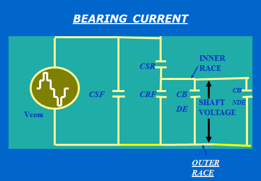
CB -Shaft to Frame Capacitance
The motor shaft rests on the bearings. When the motor rotates, the balls in the ball bearing or roller bearing float up and occupy the space between the inner and outer race of the bearing. An insulating film is formed by the lubricating medium in which a ball or roller is floating. The capacitance is transient and forms only when the motor rotates.
The value of the shaft-to-frame capacitance or bearing capacitance CB depends on the shaft speed, the type of lubricant used, the temperature of the lubricant, the surface area of the ball or roller in the bearing, and the mechanical load on the shaft. The value of the capacitance is important because the magnitude of the bearing current depends on the bearing capacitance, and the life of the bearing depends on the bearing current.
All the above parasitic capacitance is shown in an electrical model as shown below.
Mechanism behind high-frequency circulating bearing currents
The common mode voltage is responsible for the current flowing in various parts of the motor. The various currents caused to flow when a PWM inverter drives the motor are as follows. The bearing current can be categorized into four different currents according to their generation mechanism.
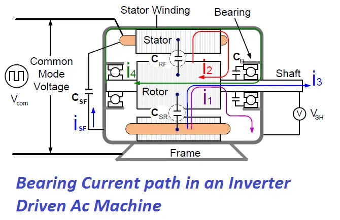
Induced AC motor shaft current & bearing failures
There are 4-types of significant current flows in VFD-driven AC motors.
1. Capacitive bearing Current(i1)
High common mode voltage causes pulse current flow to the rotor through the parasitic capacitance between the stator and rotor CSR. The current gets divided into two paths. The first path is the return path formed by the capacitance between the rotor and the frame CRF, and the capacitance between the inner and outer race of the bearing CB forms the second path. Since CSR is much smaller than the parallel combination of CRF and CB, the amplitude of i1 is smaller than the total common mode current(ISF).
However, the consistent flow of electric current through the bearing current causes heat in the lubricating system and causes the bearing to fail.
2. Electric Discharge Machining(EDM) bearing Current(i2)
An electric charge is stored in the capacitance (CRF) due to common mode voltage. The CRF is formed across the rotor body and frame. The voltage across CRF keeps building up and finally reaches such a level that it may cause the insulation of the lubricating film to break down. This dielectric breakdown results in the charge stored across CRF discharging through the insulating film of the bearing and creates EDM bearing current. The energy stored in the capacitance CRF may cause bearing damage.
4. Circulating bearing current (i4)
The circulating current flows along the axis of the rotor, through the bearings,, through the stator frame, and returns from the other bearing end. It is generally insignificant.
Preventing VFD-induced bearing damage in electric motors
The main cause of bearing damage in VFD-driven motors is the circulating current. Circulating current passing through the motor bearings needs to be prevented in order to prevent damage to the motor bearings. The following are the ways and methods to hinder the circulating current through the motor bearings.
1. Shaft Grounding Devices
Shaft grounding devices minimize shaft voltage and prevent bearing damage caused by circulating bearing current. The shaft of the motor is grounded by connecting a carbon brush between the motor shaft and the motor frame. The current finds the lowest impedance path through this circuit and does not flow through the bearing. The regular maintenance/replacement of the carbon brush is required for reliable operation.
2. Insulated bearings
An insulated bearing at the NDE side of the motor can be used to prevent the current from going through the bearing to the ground. The insulated bearing hinders the path of the circulating current, which can flow from the shaft, inner race, bearing balls or rollers, and outer race to the motor frame.
3. External passive/active common mode filters
Common mode noise filters are used to cancel the common mode noise of the system. These filters are bulky and expensive and cause voltage oscillation if passive components are not properly tuned.
3. Multi-level inverter technology
The multi-level inverter has a low common mode voltage, and thus, the bearing current gets reduced drastically.
2 thoughts on “Why Insulated Bearing is used for VFD driven Motor?”