With the help of a multimeter, we can measure quantities such as frequency, voltage, current, capacitance, resistance, temperature, continuity, etc., and check electrical and electronic components such as resistors, capacitors, diodes, transistors, cables, etc.
In this article, we will study how to measure the frequency with a multimeter and what factors can affect its reading.
Why do we Measure Frequency?
Measuring frequency is important because circuits and machines are designed to operate at certain frequencies. They operate at fixed or variable frequencies, on which the performance of machines or equipment depends.
A motor designed to operate at 50Hz will run faster if connected to a 60Hz supply. Conversely, if the motor designed for 60 Hz is connected to a supply of 50 Hz, it will run slowly.
Operating Principle of Digital Multimeter
A digital multimeter equipped with a frequency measurement feature and a peak detection circuit. The meter measures the time between two consecutive crests (wave peaks) using peak detection circuitry. It detects the peaks in the input waveform, measures the time between consecutive peaks using a timer, and calculates the frequency based on this interval.
The meter calculates the frequency using the time between the two peaks of the waveform.
Difference between Analog and Digital Multimeters
Analog multimeters can measure frequency but may not be as accurate or precise as dedicated digital multimeters designed for frequency measurement. Analog multimeters typically have a frequency range limitation and might not be suitable for accurately measuring higher frequencies.
On the other hand, dedicated digital multimeters often come with specific features and settings for measuring frequency across a wider range, including frequencies of 100 kHz or higher. These DMMs provide more accurate and reliable frequency measurements in various ranges.
Summary: While analog multimeters can measure frequency to some extent, dedicated digital multimeters are generally preferred for more precise and versatile frequency measurements, especially at higher frequencies.
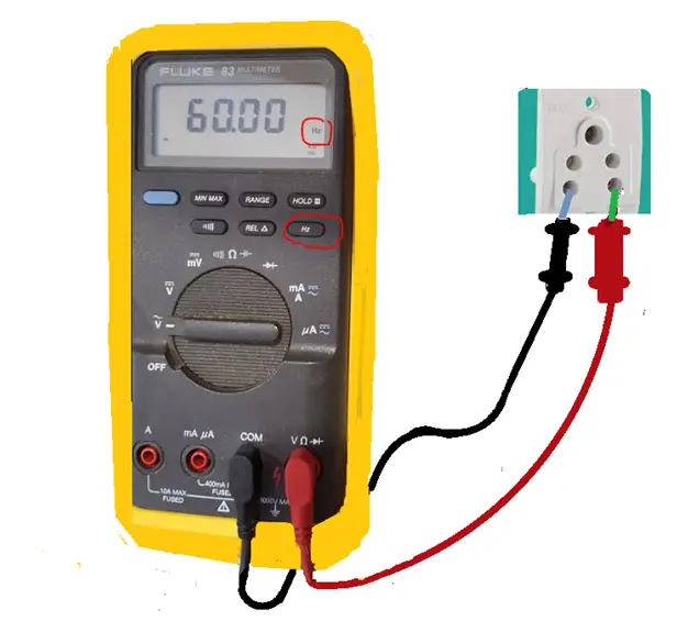
Frequency indication: Any digital multimeter that can measure frequency has “Hz” written somewhere on the dial and over the ports where the probes are inserted. They can also share a spot on the dial with “VAC” or “V~.”
How to Measure Frequency?
There are two methods to measure frequency on a multimeter.
Use this method if your multimeter has a dedicated point on the dial flow.
Procedure 1
- Turn on the multimeter by pressing the ON/OFF button.
- Turn the dial to the “Hz” option; it may share a place on the dial with any other function, such as “VAC or V~.”
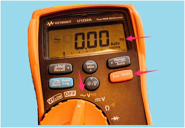
- As shown in the top figure, by pressing the shift button, we will access the secondary option, and it will begin to measure the frequency.
- “Hz” appearing on the display confirms that the meter has switched to frequency measurement.
- Insert the black test lead into the COM jack to get started.
- Insert the red lead on “VAC or V~ Port.
- The meter will display frequency Hz.
Procedure 2
Some multimeters have a point specifically dedicated to frequency measurement on the dial with “Hz” written on it.
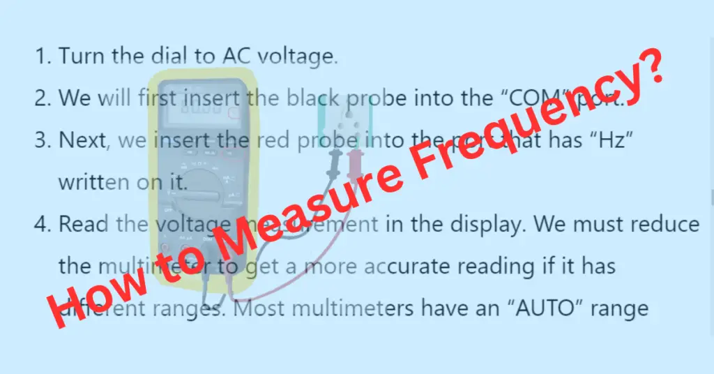
- Turn the dial to AC voltage.
- We will first insert the black probe into the “COM” port.
- Next, we insert the red probe into the port that has “Hz” written on it.
- Read the voltage measurement in the display. We must reduce the multimeter to get a more accurate reading if it has different ranges. Most multimeters have an “AUTO” range button to select the appropriate range based on the reading.
- Press the Hz button, and it will begin to measure the frequency.
- Read the frequency on the display. To indicate the measurement frequency, the symbol Hz should appear on the right-hand side of the display.
- When finished, remove the red cable and then the black one, disconnect them from the multimeter, and turn off the multimeter. This way, we will avoid possible damage in case of rapid reuse.
Problems During Frequency Measurement
The accuracy of frequency readings on a multimeter can be affected by various factors. Here are some common issues and ways to reduce them for accurate readings.
- Multimeter range
- Distortion in the input signal
Multimeter Range
The data sheet for a multimeter shows the lowest and highest frequency that the meter can accurately measure. When the input frequency falls below the specified range, the multimeter may show a reading close to the true one but not accurate enough.
The same will happen with a frequency higher than the range. Multimeters may not adjust to the actual frequency and show lower readings or show an overload “OL.”
Hence, understanding the range and estimated frequency of the input signal is essential.
Distortion in the Input Signals Filter
When the input signal experiences frequency distortion, it can impact the multimeter reading, introducing uncertainty to the measurements. The reading may also fluctuate. The signal can be filtered from the noise using a low-pass filter.
The flowing features are available in multimeters depending on the specific model.
Frequency counter mode: In frequency counter mode, the instrument counts the number of cycles of the input signal within a specified time interval and then calculates the frequency based on this count. This mode is helpful when working with electronic circuits or troubleshooting electrical systems.
MIN MAX Recording Mode: Modern multimeters are available with MIN MAX recording mode. In this mode, the multimeter records and displays a measured quantity’s minimum and maximum values, which is helpful for monitoring variation in a signal that occurs during a specific time frame.
Auto mode range: It is commonly found in electronic devices used for measuring frequencies. Auto mode range is a feature in some multimeters that allows the device to automatically select the most appropriate measurement range for the input signal being measured.
Read Next: