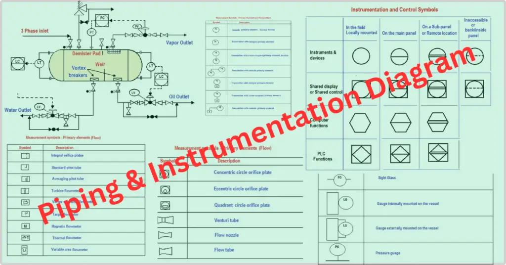
A Piping and Instrumentation Diagram (P&ID) is a detailed drawing that shows the piping and instrumentation of a processing plant. This drawing is developed during the design stage of the plant and is later used to assist in the construction and operation of the plant.
The P&IDs are fundamental for the maintenance and modifications of the process that is graphically represented in detail. A P&ID or PID uses standardized symbols and equipment to represent components related to the flow of a physical process. It is used most commonly in the engineering field.
In the design stage, the diagram also provides the basis for developing system control diagrams. It helps to study and analyze Hazardous and Operability (HAZAOP), which is an integral part of process safety management.
The P&IDs are used by stakeholders like technicians, engineers, and operators specialized in the field to better understand the process and how the instrumentation is interconnected.
Piping and Instrumentation diagrams are valuable tools and useful in training workers and contractors.
Basic Information about P&ID Diagram
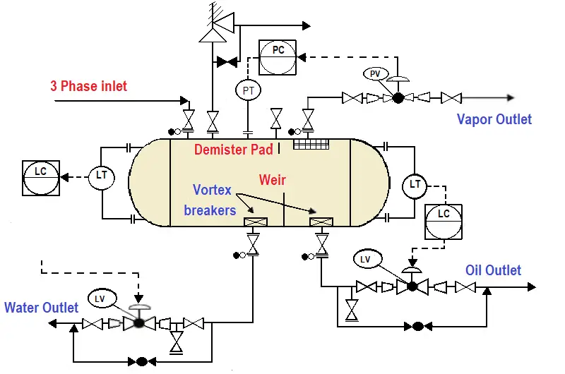
The P&IDs visually represent the functional relationship of the piping, the instrumentation, and the system equipment components used in instrumentation, control, and automation. Generally, it is designed by engineers who design a production process for a physical plant.
The P&IDs are very valuable documents that need to be handled manually and are used to simplify an existing process, replace a piece of equipment, or guide the design and implement a new installation. With appropriate data, one can plan secure and efficient changes using change of management (MOS).
How are P&IDs helpful?
The P&IDs are essential in process engineering to show the interconnectivity, but they do not necessarily include the specifications. The specifications are generally provided in separate documents.
However, it is instrumental to have many forms, among them:
- P&IDs: Help to evaluate construction processes
- Serves as a basis for control programming
- Remove and standard settings for the operation of the installations
- Develop documents that explain how the process works
- Bring a common language to discuss plant operations
- The safety of the plant can be created, which also helps its implementation
- One can design a conceptual distribution of a process plant
- Develop recommendations for cost estimates, team designs, and plant designers
Difference between a Process Flow Diagram (PFD)& a Piping and Instrumentation Diagram (P&ID)
P&ID and PFDs are engineering drawings that provide different types of information. They share some similarities, and they serve different purposes.
The details of the instrumentation vary with the degree of complexity of the design. The simplified and conceptual designs are the process flow diagrams (PFDs).
P&IDs originate from PFDs; they provide a higher level of detail. A PFD is an image of the individual steps of a process in sequential order.
A PFD shows less detail than a P&ID and is generally the first step in the process design; it is an overall view. In a P&ID, piping, and instrumentation diagrams with more detailed information can be seen.
The P&IDs are general schematic diagrams and require documents that clarify the details and specifications.
What are the limitations of a P&ID?
The piping and instrumentation diagrams (P& IDs) are graphic representations of processes with some proprietary laminations.
We cannot consider P&IDs a real model because we do not necessarily need to scale them with geometric precision.
Control system representation is minimal and does not provide any details.
Equipment start-up and shutdown details are not mentioned.
Pipe connections between the equipment are described, but specific routing is not specified in the P&IDs.
Basic information such as tag numbers, names, and general specifications of tanks and pumps are included in P&IDs. Detailed information on sizing and other design specifications are shown in separate engineering documents.
P&IDs show major instruments and control loops, not control strategies.
It is crucial to design and review the documentation that focuses on the practical aspects of the documents.
The ISA standard-Symbols
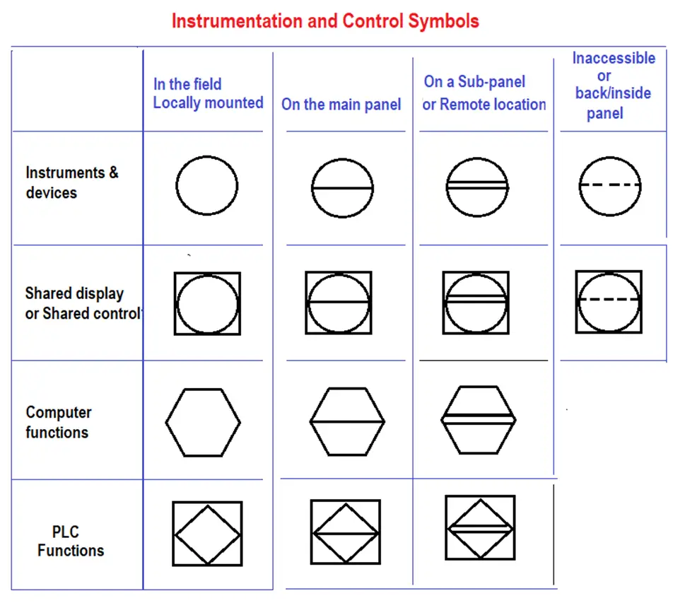
Discrete instruments, shared control, indicators, computational functions, and programmable logical controllers (PLCs) are grouped into three categories by location – in the field mounted, on the main panel mounted, mounted on remote local panel, or hidden/back/inside/inaccessible location as shown in the table below.
In the piping and instrumentation diagram P&ID diagram, the discrete instruments are represented by circular elements.
The control and indicator elements compare their circuits to a quadrant.
The computer functions are indicated by the middle of a hexagon.
The function of programmable logic controllers (PLCs) is shown as a diamond within a square.
A simple horizontal bar across the width of each of the four graphic elements indicates that the function resides in one of the primary categories.
A double line indicates an auxiliary connection and the connection of lines related to the device or function in the field.
Devices on a panel or table in another inaccessible position are shown on a pointed horizontal line.
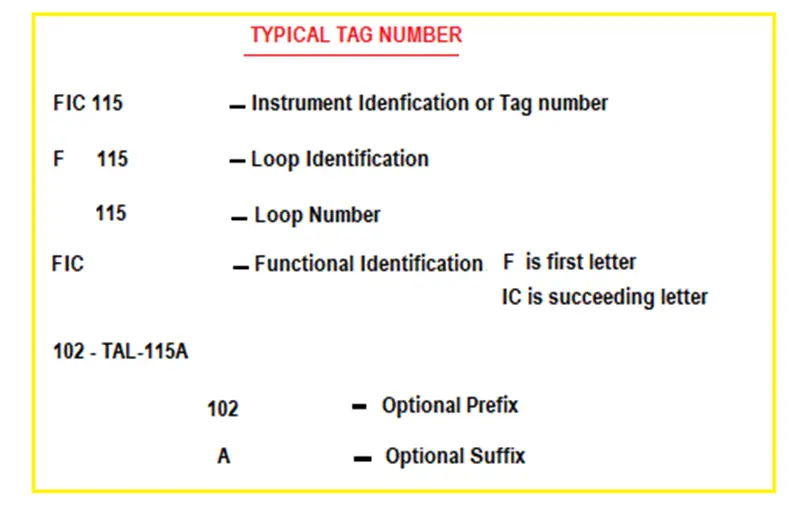
The combinations of letters and numbers appear within each graphic element, and the ISA standard defines the combinations of letters.
The first letter defines the variables it measures. Some examples include Analysis (A), Flow (F), Temperature (T), etc., with the flowing letters that define reading, pass or safety functions, Indicator (I), transmitter (T), etc.
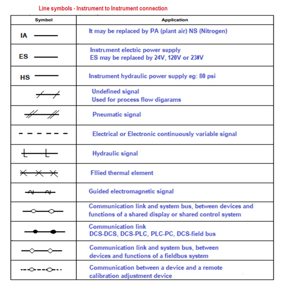
Line symbols: Instrument-to-instrument connection
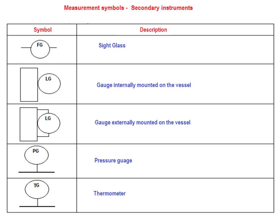
Measurement symbols – Secondary instruments
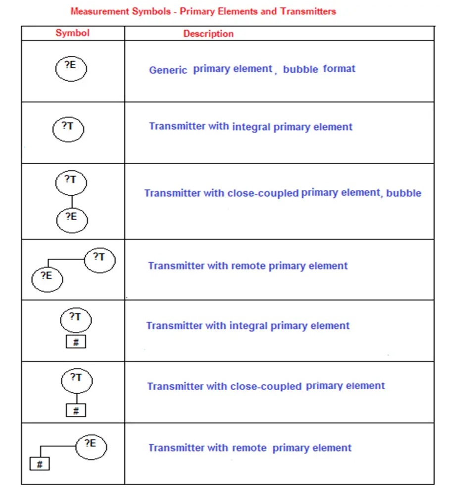
Measurement symbols – Primary elements and Transmitters
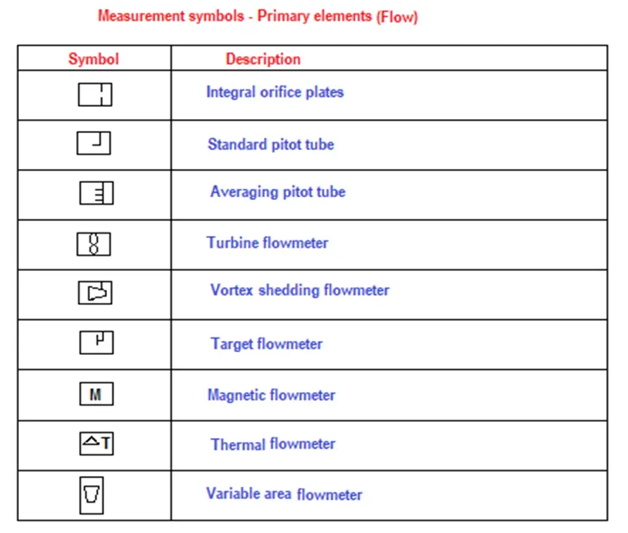
Measurement symbols – Primary elements and (flow)
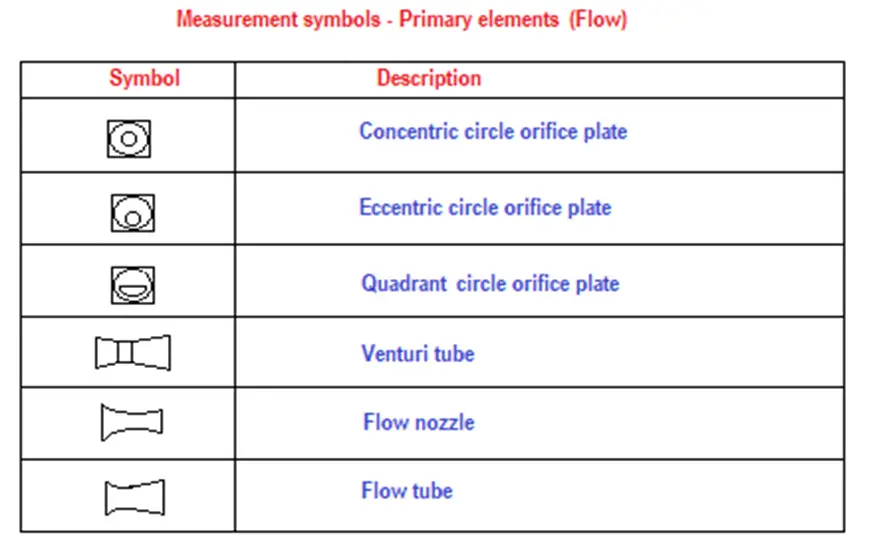
Measurement symbols – Primary elements (Flow)