This article describes cavitation and flashing in the control valve. Before understanding the phenomenon of cavitation and flashing, let us first understand the basic difference between vapor pressure and liquid pressure.
The vapor pressure of a liquid varies with temperature. As the temperature of liquid increases, its vapor pressure also increases. Conversely, vapor pressure decreases with temperature.
Under the condition of constant temperature, a change in pressure results in a transition from one phase to another. When local pressure decreases between the vapor pressure of the liquid, vaporization begins.
Flashing
In the process industry, if liquid local pressure does not recover above the liquid pressure, the liquid will remain in the vapor state. This process is called FLASHING.
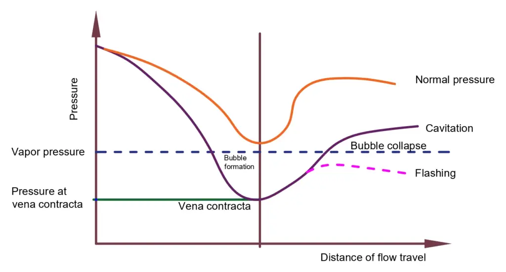
When a liquid flows through a valve and it encounters a restriction like a reduced port, it accelerates to a higher velocity to retain a constant volumetric flow rate.
If the local pressure within the restricted flow area drops below the vapor pressure of the liquid, a condition called vena contract, vaporization of fluid occurs ( vapor bubbles would form in the liquid). If the downstream pressure remains below the fluid’s vapor pressure, the process condition is called flashing.
The outlet stream is going to be in a prevailing vapor phase.
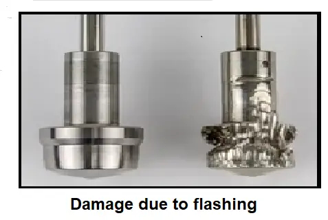
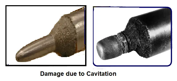
The flashing causes erosion, leading to reduced capacity of the valve. We will now discuss these problems caused by flashing in detail.
Erosion
The outlet of the valve has a flow of liquid and vapor when flashing occurs in the control valve. Thus, the vapor carries the liquid with increased flashing. On increasing the flow stream, the liquid particles that act like solid particles collide with the internal parts of the valve.
How to minimize Erosion?
- The erosion can be minimized by reducing the velocity of the outlet flow. The velocity can be reduced by increasing the size of the control valve.
- Use of hardened valve materials
- Use of an angle-body version of the valve.
- Use of a carbide or zirconia trim
Reduced Capacity
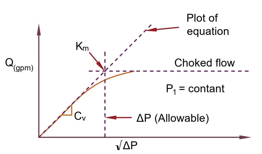
In the case of flashing, the space available for the flow stream increases because the flow stream partly changes to a vapor in the case of flashing, leading to reduced available area and further causing reduced valve capacity. In this case, the reduction in the flow capacity of the valve is termed choked flow.
Cavitation
Cavitation is a phenomenon that occurs in control valves. This causes severe damage to control valves. Shortening their life span.
Cavitation occurs in control valves in liquid media applications. When speedily approaching liquid while passing through the control valve vena contract, pressure drop takes place to a critical value which roughly corresponds to the fluid’s vapor pressure.. This low pressure causes bubbles to form and then suddenly collapse. The pressure drop caused by cavitation is shown below.
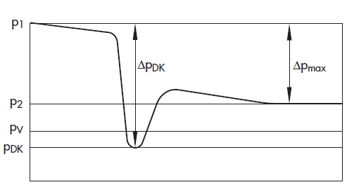
The first liquid evaporates to vapor. In control valves, if pressure drops below the vapor pressure of the liquid, then bubbles will form. These bubbles interrupt the continuous flow.
As the pressure recovers, the bubbles collapse suddenly. In this transformation, the collapsing bubbles cause damage to the valve.
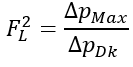
The ratio between critical pressure at the vena contracta and the vapor pressure is called the pressure recovery factor. The formula of the pressure recovery factor is;
The surface of the hydraulic components and fluid is exposed to extreme loads when gas-filled cavitation bubbles implode. For example, when bubbles collapse in hydraulic fluids, it can cause temperature rise to ignite bubbles containing air and oil vapor under certain circumstances. This process, also called the microdiesel effect, causes an accelerated aging of hydraulic fluids.
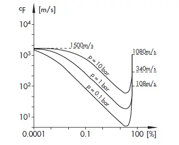
Cavitation also increases the free gas content in the fluid: Some parts of the gas dissolved in the fluid diffuse into the cavitation bubbles during the growth phase. The dissolved gas is released when bubbles collapse, and it increases the compressibility of the fluid, leading to a reduction in sound velocity, and it makes it difficult to calculate pressure surge and sound propagation in pipelines where cavitation occurs. The below figure shows the sound velocity in water as a function of the bubble concentration.
This is all about cavitation and flashing in the control valve.