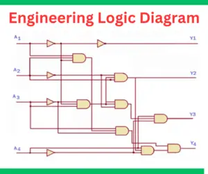
Engineering Logic Diagrams- Its Purpose and Advantages
Logic diagrams represent the relationship between logic elements in the system. The logical elements include logic gates, inputs, and signals. A logic diagram is used
Logic diagrams represent the relationship between logic elements in the system. The logical elements include logic gates, inputs, and signals. A logic diagram is used
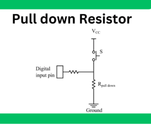
Pull down resistor is connected between the pin of the digital device and the ground. It pulls down the voltage to a logic low level.
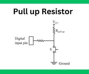
A pull up resistor is a passive element used in various digital electronic circuits to provide a reliable signal level. It is mainly used to
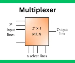
In digital electronics, a multiplexer, also known as MUX, is a combinational logic circuit widely used in various operations, such as data selection, route signals,
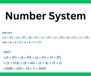
The number system in digital electronics is the fundamental concept whose knowledge is a prerequisite for learning the other concepts. As we know, digital electronics
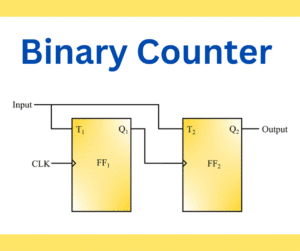
A binary counter is a digital electronic device that counts, stores, and displays the number of times a specific event has occurred. It is a
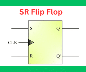
The SR Flip-Flop has two inputs( S &R) and two outputs( Q & Q’). It is also called a gated or clocked SR latch. It temporarily stores
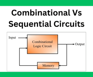
In digital electronics, logic circuits are classified into two categories namely, combinational logic circuits and sequential logic circuits. The main difference between combination and sequential
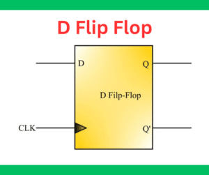
The D flip flop is the most important flip flop in digital electronics. The both inputs of the flip flop. S & R, can never
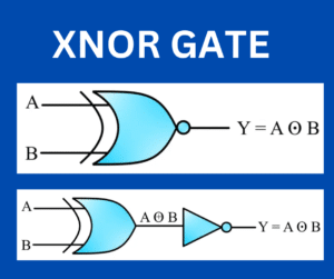
XNOR gate is a hybrid gate. It is a combination of the XOR gate and NOT gate. The XNOR gate outputs 1 when both of