Logic diagrams represent the relationship between logic elements in the system. The logical elements include logic gates, inputs, and signals. A logic diagram is used frequently to describe the flow of information between components.
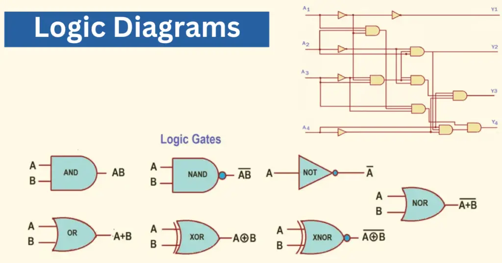
A digital circuit design involves accepting two or more values as inputs, which could be 0 or 1, and delivering output that may have an output value of either 0 or 1. The illustration that explains by graphic means is called a “logical diagram.” The logic diagram symbols are given in the below picture.
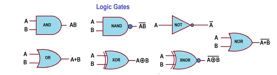
A complete digital circuit uses gates, which are electronic devices that produce a digital output depending on their nature and the type of input they receive. The control logic diagram logic gates are shown below.
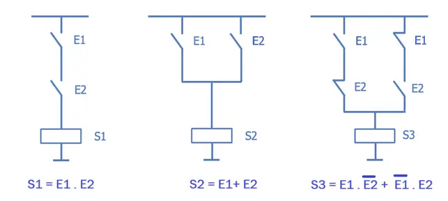
The above figure is an implementation of the basic logical functions of AND, OR, and XOR, respectively. It is a representation method that corresponds directly to the electrical connection diagram that would have to be made to build automation.
In this article, we will go into more detail about a logic diagram. Let us discuss in detail what a logic diagram is. In the following sections, we study why a digital circuit is important.
Purpose of the Logic Diagram
- The purpose of a logic diagram is to make complex logical processes to understand, analyze, and communicate.
- The logic of the control loops is much more complicated in oil and gas projects. One loop intervenes with another. It is not sufficient for a descriptive document to provide the correct information. In these cases, developing some control logic diagrams prepared by engineering could be required.
- The purpose of a logic diagram is to predict the expected output based on the alignment of the gates, delay timers, flip-flops, etc. The precise output may be calculated if we read with the appropriate truth table.
- The automation process can be designed using logic diagrams involving various inputs, conditions, and required outputs.
- While troubleshooting, the documentation of logic diagrams helps.
- We may need to use visual representations of logic diagrams to understand complex logic.
- The logic diagrams help to understand various team members such as engineers, designers, operation teams, and even other clients easily.
- The objective is to standardize and simplify control.
What is a logic diagram?
A logic diagram is a visible graphic explanation that shows how a certain task is performed with different types of gates connected. While the drawings demonstrate the gates and how they are associated, the truth tables speak of the devices’ final outputs when signals are sent to their input points.
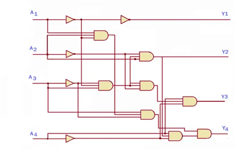
The logic diagram above is an example of a complex digital circuit connecting a pair of NOT gates and a few AND gates. The above-shown circuit is designed to accept four inputs, namely – A1, A2, A3, and A4. It is expected to produce four outputs- Y1, Y2, Y3, and Y4. When the signals are sent to the input point, they pass through the logic gates, and depending on the type of input values (o or 1) and the gates, the output is produced.
The typical logic, also called macros or functional blocks, plays a crucial role in the development of any industrial project. There are specific software engineering uses that mainly help jump from one line of logic to another page.
From the development of the “control logic,” the devices will be represented in the logic as a little box in which some signals will enter from the left, and some responses will be sent from the right.
What to do before creating a logic diagram?
1. In-depth knowledge of gates, delay timers, and counters
Knowing the logic gates, delay timers, counters, and their operation in depth is crucial before creating a logic diagram.
Gates, we also need to know their symbols to prepare accurate diagrams. Logic gates come in various types (AND, OR, NOT, etc.) and configurations (NAND, NOR, XOR, etc.).
For an example-
AND Gate is a two-input structure in which logic will appear at the output only when both inputs are high.
OR Gate describes the logical function that if any of its input is high, the output remains high.
NOT gate has a single entrance and exit. The gate functions invert the state of the input and transfer it to the output.
NAND Gate- It is simply an inverse of the AND gate. It is an AND gate with an additional NOT gate placed at the output.
NOR Gate– The operation of the NOR gate is quite simple; the output will be high when all its inputs are logic zero. It is an OR gate, with a NOT gate placed at the output, negating the state of the inputs.
XOR Gate– It will put the output high only when the inputs are different from each other.
XNOR gate – It outputs an invert of the XOR gate.
Delay timers are important in representing a system’s logic and timing aspects. Delays in certain functions coordinate the operation of different devices. Delays can be used to ensure that certain functions occur in a specific sequence. These are very important in preparing engineering logic diagrams.
On-delay timer – The output is energizing after a pre-set time delay when the input signal is applied. Off-delay timer – After removing the input signal for a specified period, the output remains active.
Counters are used to keep track of the number of batches produced and can initiate designated actions. Counters can be used for fault detection in the operation process. A counter can monitor and trigger an alarm or shutdown if the count exceeds a set limit.
Knowledge of up counter, down counter, up/down counter, synchronous counter, asynchronous counter, decade counter, ring counter, Johnson counter, etc. is desired.
2. Truth tables
One should also know how to create truth tables from a logic diagram. This will help us evaluate the result and allow us to fine-tune your illustration for the best results.
3. Understanding Circuits
In addition to having a good understanding of logic gates, we also need to know how to design circuits. Placing the gates incorrectly or connecting them to the wrong analog components could cause serious damage to the device. In addition, it results in financial loss and injury to the personnel working on the project.
4. Use a diagramming tool
The diagramming software program helps engineers to
- Speed up the entire creation task.
- The diagramming tool allows us to use perfectly designed templates and symbols from its library.
- It eliminates the need to sketch them every time from the beginning.
- The professional appearance of logic diagrams with consistent shapes, sizes, and alignment.
- It makes it easier to search through a complex diagram for specific information.
Advantages of logic diagrams
- The advantage of having a logic diagram is that it eliminates the chances of wasted time and unexpected results that engineers and designers could handle without it.
- A logic diagram, in combination with its truth table, is used to determine the exact output.
- If the technicians find any inconsistencies in the circuit, they can correct it on paper before moving on to the application.