Electrical diagrams, also known as electrical schematics, visually represent an electrical circuit using symbols and lines. They clearly illustrate how components are connected and how electricity flows between them.
Also, it can be stated that it is a pictorial illustration or pictorial representation of an electrical circuit. They are usually created by electrical engineers who help fellow engineers, electricians, and technicians in understanding electrical circuits.
Electrical diagrams help to explain simply how they are going to carry out the installation of the equipment. There are several schemes, which are graphed based on the parts of the system being represented.
It is important to note that the drawings of the diagram are agreed upon and regulated by specific regulations so that anyone can understand them.
In this article, we will focus on
- What an electrical diagram
- The types of electrical diagrams
- Importance of electrical diagram
What is an electrical diagram?
An electrical diagram is a graphic representation of an electrical circuit in which the components’ symbols and their respective connections are reflected.
The drawing is carried out by an engineer specialized in electrical engineering and has to be as basic and simple as possible.
Electrical diagram is used in a wide range of applications in industrial, residential, and commercial applications. They play an essential role in operational activities, safety, and improving the efficiency of people working with them.
Types of Electrical Diagrams
Electrical diagrams are categorized according to the specific system components they represent, and these categories include
- Electrical schematic diagram
- Electrical diagram
- Ladder logic diagram
- Electrical diagram for connections
- Electrical block diagram
- One-line or Single line diagram
1. Electrical Schematic Diagram
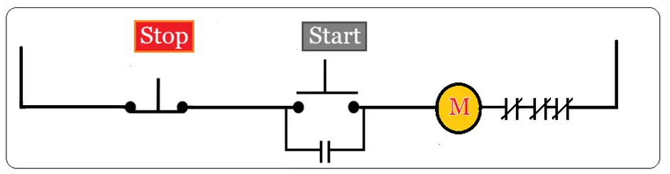
An electrical diagram is a graphical representation of an electrical system property. It uses standardized symbols to depict various components and connections in the circuit. Schematic diagrams are used to understand the structure and connections of the circuit without necessarily representing the physical layout or arrangement of components. Schematic diagrams are used in electrical engineering and various other fields to design, analyze, and troubleshoot.
2. Electrical Diagram for Wiring:

As the name implies, they represent the location of the system wiring. It is usually very common in construction, engineering, and electronic and electrical equipment manufacturing industries.
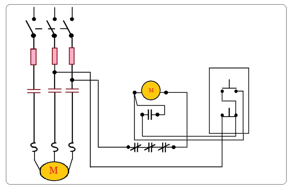
3. Linear Ladder Electrical Diagram
A Ladder diagram is a type of schematic diagram that resembles a physical ladder. It is used to represent industrial automation and control systems. In other words, it is used to explain the logic of control systems. Control logic is represented in standard symbols, rungs (horizontal lines), power rails (two vertical lines on either end), and components such as relays, switches, sensors, timers, and coils, arranged in a logical sequence to control a specific aspect of the process.
The ladder logic of the above control scheme is given below.
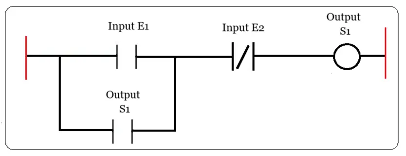
In a ladder, power travels from left to right. In a typical circuit, the contacts appear on the left side and a coil on the right side.
Contact normally open (E1)- if the associated variable E1 is ‘0’, the contact remains open, and if it is ‘1’, it is closed.
Contact normally closed (E2)-if the associated variable E2 is ‘1’, the contact remains open, and if it is ‘0’, it is closed.
Output, coil, or relay (S1) – the associated variable S1 will take the value of the variable.
The key feature of ladder logic is that it does not necessarily reflect the physical layout of the components in the real-world electrical panel. The ladder logic rung contains tag numbers of all equipment in the logic circuit with labels and little description. It helps to understand the logic and is helpful while troubleshooting.
In industrial systems, control logic is made easier for engineers and technicians to understand while troubleshooting control circuitry.
4. Electrical Schematics for Connections:
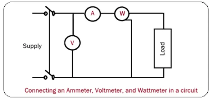
When connecting measuring instruments to a circuit, we need to follow the guidance to connect the instruments at the appropriate points to measure the desired electrical parameters such as current, voltage, frequency, etc. These measurements are used for various purposes, such as collecting data for analysis, identifying circuit performance, and diagnosing issues.
For example, power sources are indicated in the connection diagram to show where the circuit gets electrical energy. Electrical connection diagrams include symbols for measuring instruments like an ammeter, voltmeter, and oscilloscope to connect at specific points.
Connection diagrams help to design new circuits and troubleshoot identify faults in the circuit. It symbolizes the study of the connection to be made. These diagrams are of great use in our first beginnings of electrical installations.
A connection diagram is like a little draft that is done before the electrical installation. It is done on a piece of paper of any size and is useful for a small analysis of an installation, whether large or small; one of the objectives is to modify the circuit before putting it on a plane.
Let us note that these types of diagrams are used more in our beginnings of technical training since, due to the way they are drawn or created, the installation of the circuit can be easily analyzed, and they can include symbols of thermomagnetic switches indicating their protection capacity for the circuits they protect.
5. Electrical Block Diagram:
The Electrical Block diagram is a commonly used tool in various fields, including engineering, electronics, control systems, and more. It is a graphical representation used to represent the functional components of a system or process. It illustrates how they are connected. It is made up of a set of rectangles, and its function is described in it.

Its purpose is to convey the overall functionality as well as structure of a system. Various components in the electrical system are represented in blocks. The blocks include devices, circuits, or functional units. Lines connecting the blocks indicate the flow of signals. These blocks are identified by labels with names or tag numbers.
The block diagram helps and becomes an aid in communication between designers and engineers, especially when discussing the overall architecture of a system.
6. One-line or Single line Diagram
A one-line diagram, also known as a single-line diagram, simplifies the representation of three-phase power systems into a single line that shows the key components and connections.
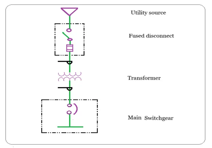
Single-line diagrams provide a simplified representation of electrical circuits and do not represent the precise electrical connections. Single-line diagrams typically use a single line to represent the electrical components and connections within a system. It often includes symbols and labels to distinguish between the three phases in a three-phase system.
A one-line diagram in electrical engineering typically provides a simplified representation of electrical systems, often used for overview and planning purposes. On the other hand, it can include various details depending on its purpose. It usually doesn’t comprehensively show the specific rating and sizes of electrical equipment, circuit conductors, or protective devices.
Why is an electrical diagram important?
Electrical schematics are indispensable tools in the electrical engineering and construction fields. They play a vital role in ensuring electrical systems safe and efficient operation right from design, installation, maintenance, and troubleshooting.
The system’s connections are reflected in it, including the components, cable colors, and the signals of each terminal. In short, every detail of the electrical system is presented in it.
The Electrical diagram is simple so that anyone can understand the drawing. An important aspect to note about the electrical diagram is that it can prevent possible breakdowns.
In the electrical diagram, the entire electrical system of a property is reflected.
How do you make an electrical diagram?
An electrical diagram must represent all the processes or steps that must be carried out for the equipment of an electricity system.
Elements will be added depending on the nature and characteristics of the circuit to be installed. An important thing is always to maintain order so that the representation is perfectly understood.
Another fundamental issue to consider is that electrical diagram drawings are agreed upon and regulated by specific standards.
Precisely, among the most used symbols in an electricity diagram, the following stand out:
- Diodes
- Coil
- Inductors
- Resistors
- Switch
- Fuses
- Cables
- Regulators
- Receiver
- Dimmer
- Electrical power supply
Summary
At present, entrepreneurs dedicated to the creation of software have launched software design programs on the market that greatly facilitate the preparation of an electrical diagram. As for drawing up the diagram, engineers have found a quick and easy way to carry out a job that was slow and cumbersome until a few decades ago.
Technological advances such as computer-aided design (CAD) software have allowed engineers to create detailed diagrams much faster and more accurately than ever before.
The eruption of technology has facilitated both the realization of the scheme and its reading by the recipient.