PLC works with four kinds of signals.- The Digital input signal, digital output signal, analog Input signal, and analog outputs signal. Digital signals are sometimes also referred to as discrete signals.
Devices such as limit switches, pressure switches, level switches, temperature switches, flow switches, and vibration switches produce a digital signal which goes to the digital input module of the PLC. On the other hand, the solenoid valve, pump start command, pump stop command, etc are the signals which are generated by the digital output module of the PLC.
Basic idea about a control loop
In industry, all the field instruments are individually connected to a junction box. From this junction box, a multi-pair cable connects to the control room. In the control room, a DCS or PLC is installed. At first, the cables are received at the marshaling cabinet.
Here, they are segregated as digital input (DI), digital output (DO), analog input (AI), and analog output (AO) cables. Fuse TBs are also in line so as to protect the system from voltage spikes. The signals then travel into the system cabinet. Here signal conditioning takes place. For digital loops, 24 VDC or 8 VDC as per requirement is used.
For analog signals, 4-20mA signals are used which are later converted to 1-5 VDC by the PLC. These signals then enter the digital and analog input-output cards and later act as input/output of the controller.
PLC Digital input and output Modules
PLC Digital Input Modules
In a process, there can be a point where only two states are possible-on and off. This is called discrete data. Some devices that have discrete data are process switches, push buttons, limit switches, and proximity switches. When a PLC/DCS must be aware of a discrete state of the sensor, it must receive a signal from the sensor. This signal comes via a discrete input channel.
Each discrete input module typically consists of a set of light-emitting diodes (LEDs) which would be energized when the corresponding sensing device turns on. The light from the LED will be incident on a photo-sensitive device, for example, a photo-transistor, that is placed inside the module.
This will generate a bit (Bit is a single element of digital data) inside the PLC’s memory. This arrangement, which is known as the Opto-couple arrangement, will make each input channel of a PLC rugged. It would make it capable of isolating the sensitive computer circuitry of the PLC/DCS from the transient voltage spikes and another electrical phenomenon capable of causing damage.
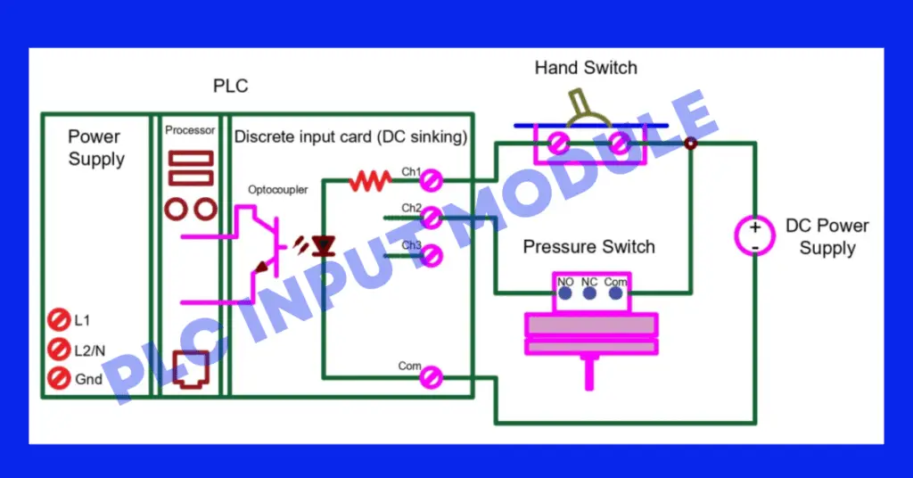
In a digital input module/input card, the internal circuitry is shown below.
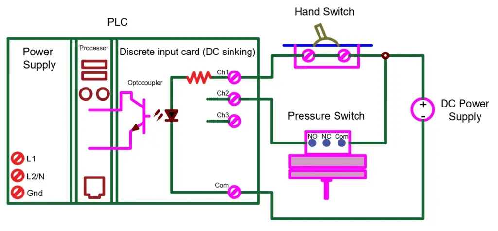
As seen in the above picture, when an input channel is energized, the LED light which is present in the optocoupler turns ON. This will turn ON the phototransistor. By this, the PLC/DCS receives a “high” signal and hence sets the bit to 1.
There is a separate optocoupler for each input channel. These write their own unique memory register bit inside the PLC/DCS memory. The digital input cards generally have 4, 8, 16, and 32 channels.
PLC Digital Output Modules
The digital output cards also have optocoupler arrangements similar to the digital input cards. Each digital output card channel has its own optocoupler arrangement. But in the digital output cards, the optocoupler has some form of optoisolator so as to allow the PLC’s computer circuitry to send electrical power to loads that are; the internal PLC/DCS circuitry which drives the LED that in turn activates the same form of the photosensitive switching device. Electromechanical relays can also be used instead of the Opto-isolating semiconductor switching elements, for example, transistors (DC) or TRIAC (AC).
The most important concept here is the distinction between current sourcing and current sinking. These refer to the direction of flow of current into or out of the device’s control wire.
Sourcing Current: The device which sends the current out of its control terminal to some other device is said to be sourcing current. (The current flow considered here is the conventional flow of current)
Sinking Current: The device which receives/accepts the current into its control terminal to some other device is said to be sinking current. (The current flow considered here is the conventional flow of current)
The control wire here means the single conductor which connects the I/O card channel to the field device. The conductor is directly common with the positive and negative lead of the voltage source. When this single wire is taken into consideration, the direction of the current flowing through it shows whether it is a sinking current or a sourcing current. It becomes easier to identify the type of current in such a case.
This is all about PLC Digital Input and Digital Output Modules.
Read Next: