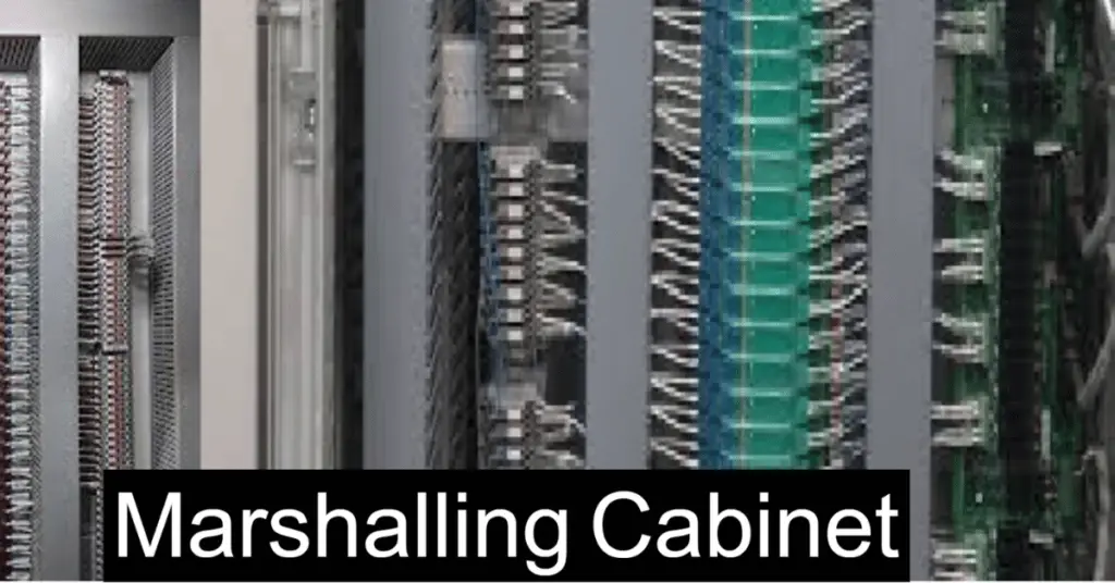
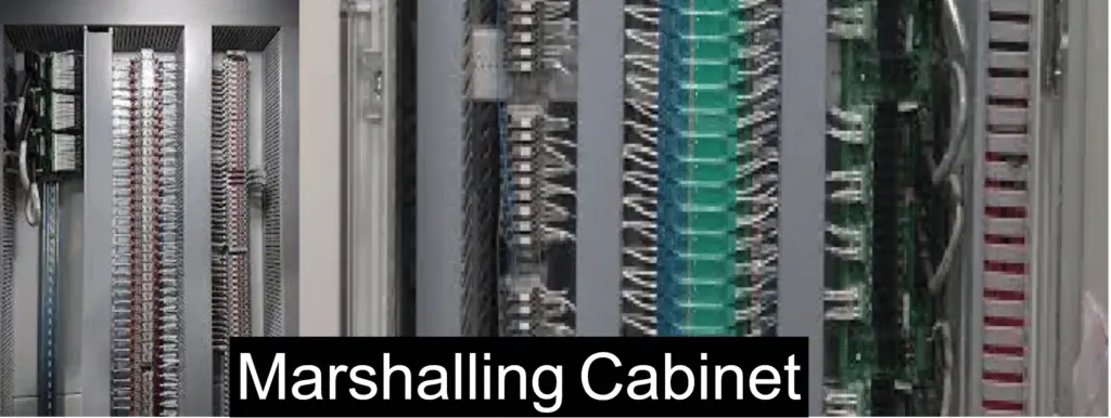
The marshalling cabinet or field marshalling panel acts as an interface between the system cabinet of DCS and the field junction boxes. The main cables from the field junction boxes are laid to the marshalling cabinet. The prefab cables from the system cabinet input and output cards are also terminated in the marshalling cabinet.
The marshalling cabinet serves as the primary termination point for incoming field cables. The incoming field wire is generally a multipair cable. After getting terminated in the marshalling cabinet, the other ends of wires are connected to the system cabinet internally where the I/O cards and controller are installed.
Why is Marshalling cabinet important?
If the marshalling cabinet is not installed, there can be problems for the operating personnel in maintaining and operating wiring.
The most important interface function of the marshalling cabinet is the cross-wiring function. Cross-wiring is necessary because the incoming field signal and the channel quantity of the card are always different. For example, there is an incoming 24-pair field cable which carries 20 field analog signals.
This field signal would be split at least into two analogue cards with 16 channels. The first 16 I/O would be connected in the first 16 channel I/O card and the remaining 4 I/O signals will be connected in the next 16 channel I/O card. From the operation and maintenance point of view, it is not advisable to have this split wiring (cross-wiring) in the system cabinet. Hence, the marshalling cabinet is required.
Another reason for cross-wiring can be the mix of I/O signals which is coming from the incoming multipair cable. The incoming cable can carry mixed analog input (AI) and analog output (AO) signals. Marshalling cabinets can also have digital input (DI) and digital output (DO) signals.
This mixed signal is split in the marshalling cabinet so that the AI signal can be terminated in the dedicated AI termination board. In the same way, the AO signal is terminated in the dedicated AO termination board. In the case of DI signals, termination is done at the dedicated DI termination board.
Cable Routing In Marshalling Cabinet
In a typical application, the marshalling cabinet can have the following cable routing.
- The multipair field cable will enter the marshalling cabinet through the bottom of the cabinet.
- Each wire of the incoming multipair field cable will be terminated in the surge protection device (also known as a surge arrester). If the surge protection device is not needed, then each wire is terminated in the terminal block.
- In the non-intrinsic safe application, cross-wiring from the surge protection devices will match the field signal and the I/O address assignment in the termination board. If the system is intrinsically safe, before the cross-wiring, each wire connection is routed first to the IS Barrier.
- Then a dedicated system cable is routed from the termination board to the I/O card in the system cabinet. This cable has a plug-and-play connection.
- Some termination boards may need a dedicated DC power supply which can be taken from the DC power supply in the marshalling cabinet.
Different Types of Marshalling Cabinet Types
The different types of marshalling cabinets are:
1. Conventional Marshalling Cabinet
The conventional marshalling cabinets consist of isolators/barriers, relays, terminal blocks for field run cables, shield terminals, a terminal board that is used for cross-wiring, a power supply module and the diode O-ring.
When there is a large I/O system, a dedicated marshalling cabinet is used. When such is the case, the marshalling cabinets can be sent to the site in the early phase of the project. This will allow the termination of field cables in the initial stage itself. The system cabinets can be delivered at a later stage. After this, the prefabricated cables (prefab cable) can be installed between marshalling and system cabinets. So, when there are separate cabinets, there is an added advantage of staged factory acceptance tests and staged delivery. However, the installation of prefab cables requires fieldwork.
In the conventional type of cabinets, when FAT (Factory Acceptance Tests) for the system and marshalling cabinet are done together then the connection between both cabinets is removed when the marshalling cabinet is being shipped to the site. After the delivery, the connections between the marshalling cabinet and I/O terminals are redone.
2. System cum marshalling cabinet
The major components in the system cum marshalling cabinet are controllers, I/O modules, power supply modules, diode O-rings, and isolators/barriers. Relays, terminal blocks (they are for the field run cables/ main cables), shield terminals, and terminal board (for cross-wiring).
System cum marshalling cabinet is used for a less I/O system. It is usually packaged with control panels. System cum marshalling cabinets have controllers, I/O modules, terminals, relays, barriers, etc. installed in one cabinet. In the System cum marshalling cabinet, the prefabricated cables are pre-installed.
3. Electronic Marshalling Cabinets
In electronic marshalling cabinets, the field cables are directly connected to I/O modules. This is done based on the universal I/O concepts. Here in electronic marshalling cabinets, the terminal blocks, cross-wiring and prefabricated cables are eliminated. The I/O type is configured by using the software.
When there is an intrinsically safe design, the I/O card has a barrier slot for installation or related adaptors for field cable termination on the I/O card itself. Electronic marshalling cabinets are the latest technology in control systems. Electronic marshalling cabinets need less effort at the site, less fieldwork, and a few cabinet footprints. They also have the flexibility for spare channels.
Some very important points to keep in mind while selecting marshalling cabinets:
- Marshalling cabinets should have proper air ventilation/circulation for cooling. Not having proper air ventilation/circulation can cause heating inside the panel and damage the components.
- At least 30% free space for future expansion should be provided.
- Terminal blocks should have proper spacing so that work on any terminal block can be done easily while the plant is in running condition.