Understanding the EMF equation of transformer is essential to grasp how transformers work. When a sinusoidal AC voltage is applied to the primary coil, it creates a magnetic flux that links with the secondary coil and induces an EMF.
Introduction to EMF in a Transformer
EMF equation of transformer is very important for understanding the working of the transformer. When a sinusoidal voltage is applied to the primary of the transformer it draws magnetizing current to set up flux in the core.
The flux links to the secondary and produces EMF. We can easily derive the EMF equation of the transformer by calculating the rate of change of the flux in one cycle of the AC waveform. Induced EMF in the primary and secondary of the transformer also depends on the turn ratio of the transformer.
Understanding Voltage and Turns Ratio
The ratio of secondary EMF to primary EMF is called the voltage transformation ratio of the transformer.
The ratio of primary turns to secondary turns is called the transformer turns ratio(TTR).

How Flux Links in Transformer Windings
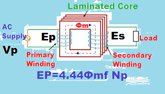
When an alternating voltage is applied to the primary winding, it produces a sinusoidal magnetic flux in the transformer core. This flux links both the primary and secondary windings, inducing an electromotive force (EMF) in each according to Faraday’s Law.
The magnitude of the induced EMF depends on the number of turns in the winding and the rate at which the magnetic flux changes. As per Lenz’s Law, the induced EMF always acts in a direction that opposes the change in the applied voltage.
EMF Equation of Transformer & Its Derivation
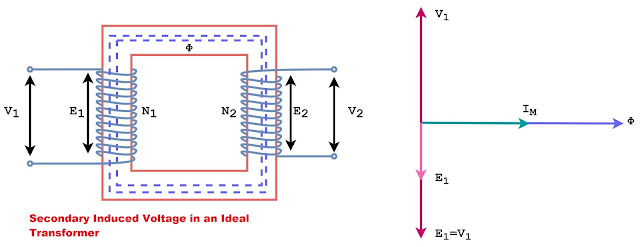
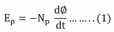
The voltage induced in the primary and the secondary winding of the transformer is shown in the image below.
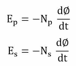
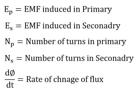
Where,
The minus sign shows that the voltage induced in the primary and secondary opposes the applied voltage.
Step-by-Step Derivation of EMF Equation of Transformer
The EMF equation of a transformer is derived by calculating the rate of change of sinusoidal magnetic flux in the core.
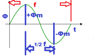
Change of Flux in One Cycle
The flux in the core changes from + Фm to -Фm in 1/2f seconds.
The voltage induced in the primary is
The flux induced in the primary is because of the sinusoidal voltage applied to the primary so the flux also varies in a sinusoidal manner.
Instantaneous Flux Equation
The instantaneous value of the flux in the transformer is ;
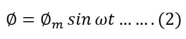
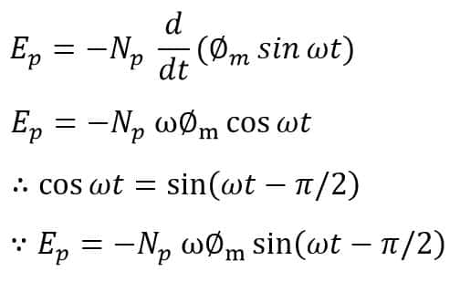
Putting the value of flux in the equation (1)
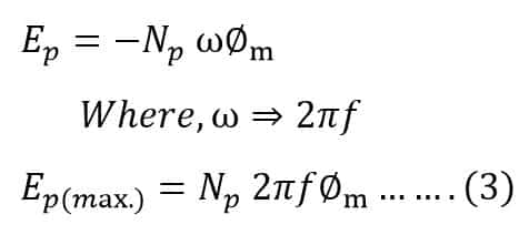
Maximum and RMS EMF in Primary
The maximum value of voltage induced in the primary is
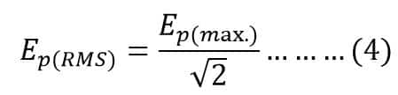
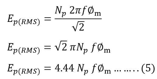
The root mean square (RMS) value of the induced voltage in the primary
Putting the Ep(max) value in equation(4)
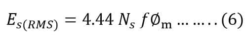
RMS EMF in Secondary
Similarly, the root mean square (RMS) value of the induced voltage in the secondary is ;
Final EMF Equation of Transformer
The general EMF Equation of the transformer is;
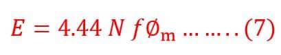
Voltage Transformation Ratio of Transformer
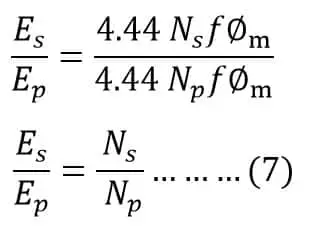
The ratio of the secondary turns to primary turns is known as the voltage transformation ratio of the transformer and it is denoted by the letter ‘K’.
Dividing equation(6) by equation(5)
If the secondary turns are more than the primary turns, the secondary voltage will be higher than the primary voltage and the turns ratio (K) is greater than 1. The transformer that has a voltage transformation ratio of more than 1 is called a step-up transformer.
If the voltage transformation ratio (K) is less than 1, the transformer is called a step-down transformer.
MMF Equation of Transformer
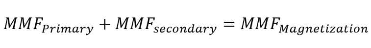
When substantial current flows through the primary and secondary windings of a transformer, the magnetizing MMF becomes negligible.
Under these conditions, the combined MMF of the primary and secondary windings balances the magnetizing requirement. The transformer maintains a nearly constant core flux as long as the supply voltage and frequency remain unchanged.
When the transformer is substantially loaded, the magnetizing MMF can be neglected.
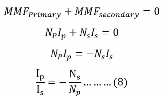
The negative sign shows that the current in the primary and secondary winding are in opposite direction with respect to the magnetizing current. The minus sign can be dropped for the calculation of the transformer transformation ratio.
From equations (7) & (8)
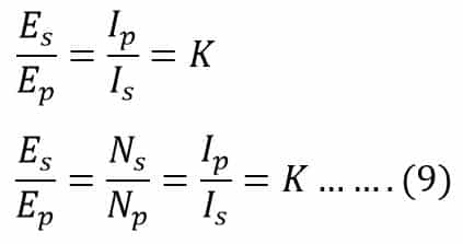
Here, K is the voltage transformation ratio of the transformer.
The voltage transformation ratio equation (9) of the transformer is true if the flux in the transformer core is constant. The flux in the transformer changes if the supply voltage and or frequency gets deviates from its designed value.
Transformer Turns Ratio
The ratio of primary(Np) to secondary turns(Ns) of the transformer is known as the transformer turns ratio or TTR. It is denoted by the letter ‘a’.
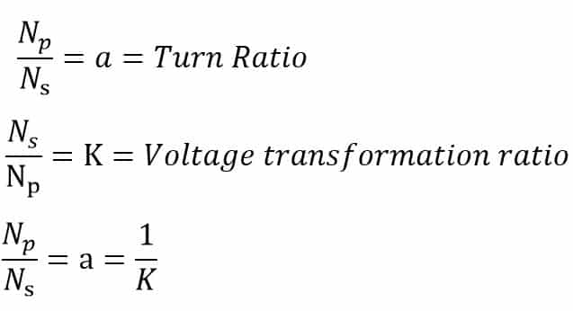
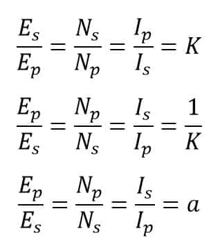
Now, we can write the turn ratio and voltage transformation equations as;
Read detailed article on: Turn Ratio of Transformer- Definition, Formula, Solved Problems
Solved Problems on Transformer EMF Equation
A two-winding transformer has primary winding with 300 turns and secondary winding with 10 turns. The primary winding is connected to a 3300 V supply system. Calculate-
- The secondary voltage at no load
- Primary current when the 100-amp load is connected to secondary
- Apparent power flowing in the primary and secondary circuit
- Turns ratio and voltage transformation ratio of transformer?
First transformer law:
The secondary voltage at no load:
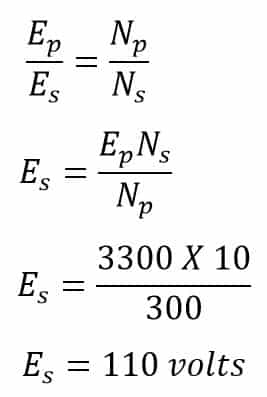
The secondary voltage at no load= 110 Volts
Second transformer law:
Primary current when the 100-amp load is connected to secondary
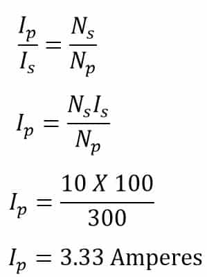
Primary current = 3.33 Amperes
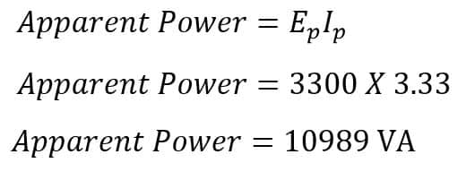
Apparent power in the primary circuit
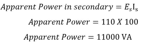
Apparent Power in the secondary circuit
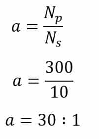
Transformer turns ratio(TTR)
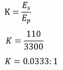
Transformer voltage transformation ratio
Related Articles: