
What is a Dry Contact? Its Characteristics and Advantages
A dry contact is a simple electrical interface that does not carry voltage or current but is used to control the flow of electricity in
A dry contact is a simple electrical interface that does not carry voltage or current but is used to control the flow of electricity in
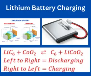
Lithium batteries necessitate a charging algorithm that upholds a constant current constant voltage (CCCV) during the charging process. In other words, a Li-Ion battery should
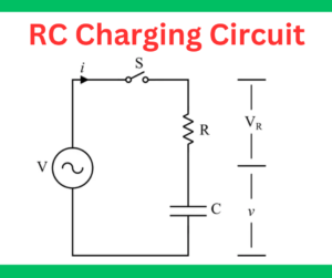
This article describes the RC charging circuit and RC network time constant. A capacitor does not instantly charge, and the voltage across the capacitor builds
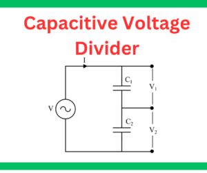
In this article, we will learn about capacitive voltage divider. As we know, a voltage divider is a circuit that is used to provide multiple
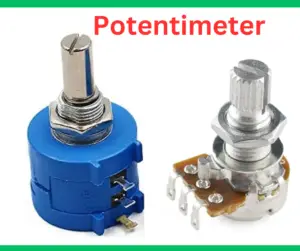
A potentiometer is a 3-terminal variable resistor whose resistance can be manually adjusted to control the flow of electric current. It is also called a pot or
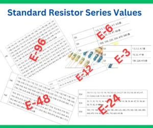
Standard resistor series values, including E3, E6, E12, E24, E48, and E96, are used to find the ideal components for your electronic projects. The E-series

An Abrasive cleaner is a cleaning product that contains abrasive materials and physical abraders designed to remove tough stains, dirt, grime, and residues from various
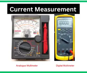
This article describes the procedure of current measurement with a multimeter. A multimeter is a device used in electrical and electronic circuits to measure a
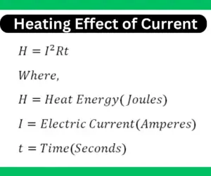
The heating effect of electric current is an important phenomenon that is used in our daily lives. When electric current flows through the resistive element,
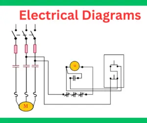
Electrical diagrams, also known as electrical schematics, visually represent an electrical circuit using symbols and lines. They clearly illustrate how components are connected and how