A circuit is described as a network loop through which an electric current or magnetic field passes. The main circuit components include – the source, conducting path, and load. In other words, any closed loop across which electricity, magnetic flux, data, or signals flows is called a circuit.
Based on the type of quantity (i.e. electric current or magnetic flux) flowing through the closed conducting loop, a circuit can be of the following two types:
- Electric Circuit
- Magnetic Circuit
In this article, we will be talking about the differences that set an electric circuit apart from a magnetic circuit. In addition to this, a brief introduction to electric circuits and the magnetic circuit is given in this article.
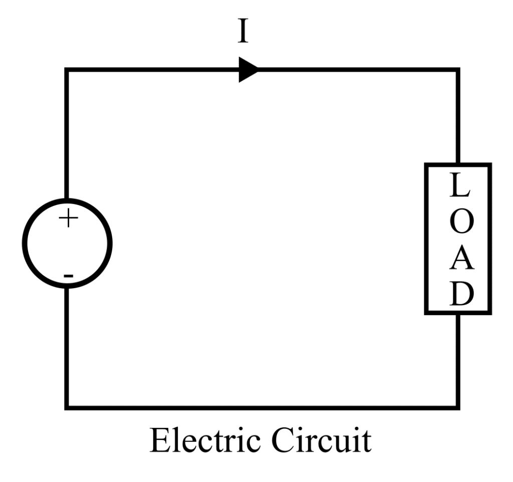
What is an Electric circuit?
An electric circuit is described as an electric network that conducts electricity. An electric circuit is comprised of – an electric source of energy such as batteries, cells, etc that drive the operation of various circuit elements, connecting wires, and mechanical or electronic loads such as lamps, bulbs, fans, etc.
Based on the nature of electric current flowing across the electric circuit, it can be categorized into the following two categories –
- DC circuit – It is an electric circuit that is supplied with a direct current source.
- AC circuit – It is an electric circuit that is supplied with an alternating current source.
Depending on the kind of circuit connection existing between the different electronic components in the electric circuit, it can be further subdivided into the following three types.
- Parallel electric circuit
- Series electric circuit
- Series and parallel circuit combination
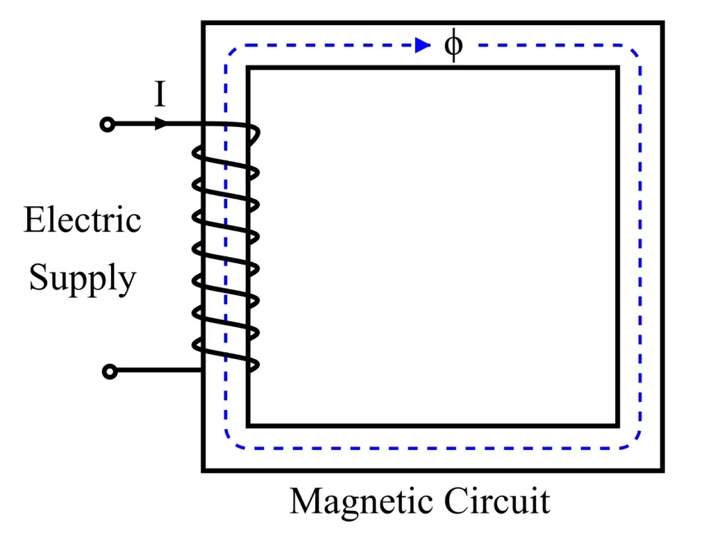
What is a Magnetic circuit?
Magnetic Circuit is defined as the closed conducting path through which magnetic flux is carried. The magnetic circuit is comprised of a highly magnetic core like soft steel or iron. The magnetic core is wound by a conducting coil, due to which a magnetic field is generated around the coil.
Magnetic circuits find a wide range of applications such as in the design of numerous electronic devices namely generators, motors, transformers, etc. Based on the arrangement of the magnetic circuit, it can be categorized into the following two types:
- Parallel magnetic circuit
- Series magnetic circuit
A parallel magnetic circuit is comprised of more than one magnetic loop for the flow of magnetic flux. While a series magnetic circuit is made up of only a single magnetic loop for the flow of magnetic flux.
Difference between Magnetic and Electric Circuits
The table below lists the major differences between an electric circuit and a magnetic circuit:
| Criteria of Difference | Electric Circuit | Magnetic Circuit |
| Definition | An electric circuit is described as a closed path carrying electric current. | A magnetic circuit is described as a closed path carrying magnetic flux. |
| Circuit parameters | An electric circuit has various measuring parameters namely voltage, current, capacitance, inductance, resistance, etc. | The magnetic circuit has various measuring parameters namely magnetic flux, reluctance, magnetomotive force, etc. |
| Field lines | Electric field lines do not form a closed loop. | Magnetic field lines form a closed loop starting from the north pole and ending at the south pole of the magnet. |
| Flowing quantity | The quantity flowing across an electric circuit is the electric current. | The quantity flowing across a magnetic circuit is the magnetic flux. |
| Units | The unit of electric current is ampere(A). | The unit of flux is weber(wb). |
| Expression | Ohm’s law describing the relation between resistance, current, and voltage in an electric circuit is given below.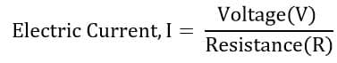 | Ohm’s law describing the relation between magnetic circuit components is given below.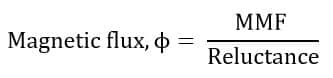 |
| Driving force | In an electric circuit, the electric components of the circuit are driven by the electromotive force, generating a voltage drop, and allowing the flow of current in the circuit. | In an electric circuit, the components of the magnetic circuit are driven by the magnetomotive force, allowing the flow of magnetic flux across the magnetic core. |
| Opposing force | The opposing force of the electric current flow is offered by the circuit resistance. | The opposing force of the magnetic flux flow is offered by the circuit reluctance. |
| MMF and EMF | Electromotive force EMF in the electric circuit is;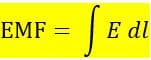 It is measured in volts. | Magnetomotive force in a magnetic circuit is;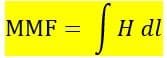 It is measured in AT(ampere Turns) |
| Variation of Resistance and Reluctance | The value of the resistance in an electric circuit is constant and it depends on the resistivity(ρ) of the material. The value of resistance changes with a change in temperature. | The reluctance of the magnetic circuit is not constant and it changes with a change in the value of magnetic flux density(B). |
| Energy in the circuit | Energy in the form of heat expands continuously in the electric circuit if the electric current flow continuously in the circuit. | The energy is consumed while setting up of magnetic flux in the magnetic circuit. After that, no energy expands, and the magnetic circuit takes a small amount of energy to create flux in the circuit. |
| Applicable Laws | The electric circuit follows Kirchhoff voltage and current KCL and KVL law. | The magnetic circuit follows Khirchhoff flux and mmf law is followed |
| Flow of electric current & Flux | The electric current flows from the positive to the negative end of the voltage source. | The magnetic flux originates from the North pole and ends at the South pole. |
| Flux and Electrons | The electric current flows in the form of electrons in the electric circuit. | Molecular poles get aligned in the magnetic circuit. |
| Drops | Voltage drop = IR | Mmf drop = φS |
| Expression of opposing force | The expression for the resistance offered to the electric current is given by the following formula. | The expression for the reluctance offered to the electric current is given by the following formula.  |
| Examples | Glass, air, rubber, PVC, and synthetic resin act as perfect insulators for the electric circuit, and these insulators do not allow the current to pass through them. | There are no perfect insulators for a magnetic circuit. The magnetic flux can be set up in insulators like air, rubber, PVC, glass, etc. |
| Inverse of opposition | The reciprocal of the resistance offered is called as the conductance and is given as follows.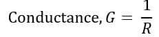 | The reciprocal of the reluctance offered is called as the permeance and is given as follows.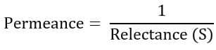 |
| Density | The density of electric current is referred to as current density.  | The density of magnetic flux is referred to as magnetic flux density.  |
| Intensity of the applied field | The intensity of the electric field is given by the following expression. | The intensity of the magnetic field is given by the following expression.  |
Conclusion
In conclusion, this article discusses the prominent differences between an electric circuit and a magnetic circuit in terms of various factors such as Ohm’s Law, the intensity of the applied field, field lines direction flow, drop, etc. Both electric and magnetic fields are used widely in the manufacturing of several electrical machines and devices.