The main reason why a single-phase induction motor is not self-starting is that it produces a revolving magnetic field and not a rotating magnetic field. In this article, we will understand the concept of this.
Single-phase induction motors are mainly used in fans and blowers. These fractional-kilowatt machines are not suitable for driving loads but are efficient and economical for low-power applications like fans or blowers.
However, unlike their three-phase counterparts, single-phase induction motor is not self-starting which is one of the disadvantages of this motor. Here we will discuss about the working of these motors and why they are not self-starting. In addition to that, we will briefly discuss the techniques employed to get them self-started.
Working
Our homes, offices and other such places need low power appliances and hence we have a single-phase supply from the distributor. One of the most common things we need is fans and as it has to operate on this single-phase supply, therefore the motor used in them should be reliable, efficient, and economical for that application. Single-phase motors meet all these criteria. Let’s understand the working of this motor.
A single-phase induction motor has three important parts – the Stator, the rotor, and the windings. The stator houses the stationary windings through which a single-phase AC current is supplied from the source. As a result, a corresponding magnetic field is generated in the air gap between the stator and the rotor.
However, this magnetic field is not a rotating one like that in the case of a three-phase induction motor. This field links with the rotor windings. As the supplied voltage is alternating in nature, the air gap magnetic field is also an alternating one. This time-varying magnetic field causes the generation of induced EMF in the rotor conductors according to Faraday’s law of electromagnetic induction.
According to Lenz’s law, the induced EMF tries to neutralize this change by trying to rotate. However, the rotor fails to rotate or self-start which can be explained by the Double Rotating Field Theory.
Double-Revolving Field Theory
In the case of a three-phase induction motor, all three phases remain 120 degrees apart at any point in time. If the three-phase source voltage or the corresponding air-gap field is plotted with respect to time, we will see that the resultant field is a rotating one which therefore induces a rotating field in the rotor and hence the rotor follows this rotating field to neutralize its effect. Therefore the rotor begins to rotate naturally. That doesn’t happen in the case of a single-phase induction motor as the supply is only one-phase alternating current which alternates every half cycle and the resultant force generated is zero.
The Double-Revolving field theory explains the entire phenomenon. Single-phase AC supply causes the generation of two counter-rotating magnetic fields in the air gap. Both of these fields are equal in magnitude but opposite in direction. This equal and opposite magnetic field is generated due to the AC voltage being in the positive and negative half cycle alternatively.
Therefore the rotor faces both clockwise and anti-clockwise rotating air gap magnetic field which therefore tries to move the rotor in their respective direction. But both being equal, the resultant rotating force becomes zero and fails to overcome the inertia of the rest of the rotor. The picture below is the graphical representation of this theory.
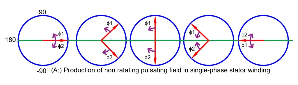
As you can see, the air-gap magnetic field is divided into two fields of equal magnitude but opposite in direction to each other at any instant of time. The vector sum of both these fields will decide the direction and magnitude of the rotation of the motor.
As the fields are equal and opposite, they cancel out each other’s effect causing the motor to remain at standstill. For the motor to rotate, it has to be forced externally in any one direction so that this balance of force in both directions breaks and the motor begins to rotate.
This can be done physically by applying a force however it is not desirable because in many applications, there might be no direct access to the motor or it might be loaded. Therefore there should be some mechanism in the motor circuit itself to allow the motor to break this balance of force itself and start rotation in any one direction.
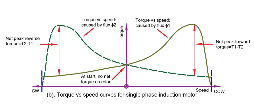
The picture above shows the Torque-speed characteristics of the single-phase induction motor. Both the oppositely revolving magnetic fields create their corresponding starting torque which cancels out leaving no torque at the start.
Another theory explaining why single-phase induction motors aren’t self-starting is the Cross-field Theory.
Cross-field Theory
Cross-field theory is a closer manifestation of what happens within a single-phase induction motor that restricts its motion during start.
Let’s assume that the motor is at a standstill when it is supplied with the single-phase AC supply at rated voltage. This causes the production of a single-phase alternating magnetic field flux in the stator windings along its axis.
This magnetic field links with the rotor windings through the air gap by the transformer action; hence, an emf is generated in the rotor windings. As the rotor is a closed circuit, this induced emf causes a current to flow through the rotor circuit.
By Lenz’s law, we know that this induced emf tries to kill the very cause of its own creation, Therefore, the current through the rotor flows in such a way that the rotor magnetic field flux opposes the air gap field to maintain the status quo. The direction of the rotor current can be determined by Fleming’s left-hand rule.
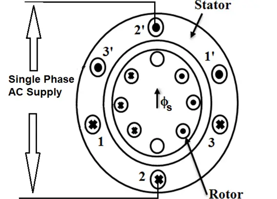
The picture shows the direction of the current induced in the rotor. It can be seen that when the air gap magnetic field Φs is in an upward direction, the rotor conductors on the left-hand side induce such a current that it forces the rotor to rotate from left to right while the conductors on the right-hand side experience a force from right to left.
As both these forces are equal and opposite in direction, it causes the net effect to be zero on the rotor and the rotor remains at standstill. That’s why the motor is not self-starting.
To overcome this, an external force is required which causes the rotor conductors to cut the stator air gap magnetic field and generate a rotational emf. This causes the rotor conductors to generate a current which further creates a magnetic field flux of itself. Thus, the balanced force breaks, and the motor gains starting torque and it begins to rotate in its direction.
How to make a single-phase induction motor self-starting?
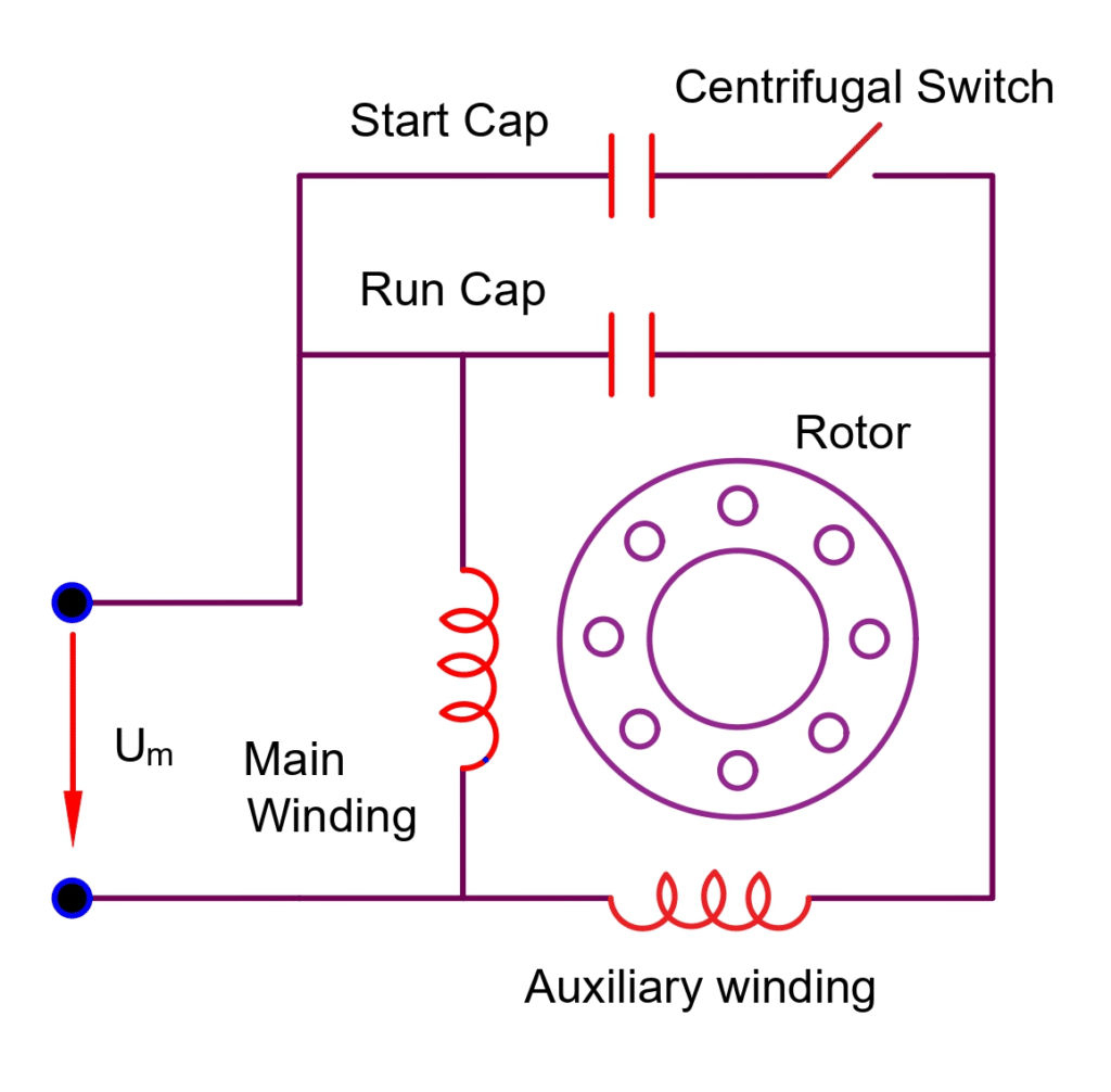
The main aim of any starting mechanism is to provide an imbalanced torque to the rotor to allow it to rotate. One such mechanism is the split phase technique. In the split phase technique, the stator carries two windings – The main winding and the auxiliary winding. The auxiliary winding is connected with a capacitor or resistor while the main winding is simply an inductive circuit.
When supplied with AC current, both the windings generate their respective magnetic field. In the main winding, the current lags the supply voltage by a greater angle whereas, in the case of the auxiliary winding, the resistor or the capacitor connected in the circuit causes the angle between both the voltage and the current in the winding to reduce.
Thus, there are two types of induced current that result in the generation of two types of air gap fields separated by an angle. This looks like a 2-phase or split-phase supply which easily allows the motor to start.
Once the motor gains the required speed, the auxiliary circuit is cut out by a centrifugal switch. However, keeping it connected while running increases the motor’s efficiency and performance.
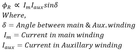
In most of the applications, the capacitor split phase is preferred as compared to the resistor split phase as the resultant magnetic field and thus the rotating force depends on the sine of the angle between both the fields generated by the main and the auxiliary windings. Therefore, the higher the angle, the more efficient the motor operation will be.
While the resistor brings the voltage and the current in phase, the capacitor causes the current to lead to the voltage. In this way, the angle between the auxiliary winding field flux and the main winding field flux increases and reaches almost 90 degrees which are ideal for the required operation.
Apart from the split phase, there are various other methods to start a single-phase Induction Motor like shaded pole start, Reluctance start, and repulsion motor start. However, none of them comes closer to the type of performance that the split-phase start provides.