In this article, we will learn about different types of single-phase induction motors, their construction, working, and applications.
An induction motor is a type of asynchronous AC motor in which the required working torque is produced by electromagnetic induction. It is an asynchronous motor because its rotor always rotates at a speed slightly less than the synchronous speed of the rotating magnetic field.
Depending on the type of input AC supply, the induction motors are classified into two major types namely,
- Single-Phase Induction Motor
- Three-Phase Induction Motor
As their name implies, a single-phase induction motor requires 1-phase AC for its operation, whereas a three-phase induction motor requires a 3-phase AC supply for working.
The major problem associated with single-phase induction motors is that they are not self-starting. Hence, it is required to provide additional magnetic flux to make them self-starting by employing some mechanism. Therefore, based on the method used to provide additional flux, i.e. method of self-starting, the single-phase induction motors are classified into the following major types:
- Split Phase Induction Motor
- Capacitor Start Induction Motor
- Capacitor Start Capacitor Run Induction Motor
Split Phase Induction Motor
A split phase induction motor is a type of single-phase induction motor which has two windings namely starting winding and running winding displaced by 90° from each other. Therefore, the major parts of a split-phase induction motor are starting (or auxiliary) winding, running (or main) winding, and a centrifugal switch.
The split phase is the simplest method for producing a rotating magnetic field which is used in this motor. In this method, both starting and running windings are placed on the same stator core. In the case of a split phase induction motor, the starting winding is made highly resistive while the running or main winding is made highly inductive. The circuit diagram of a split-phase induction motor is shown in the following figure.
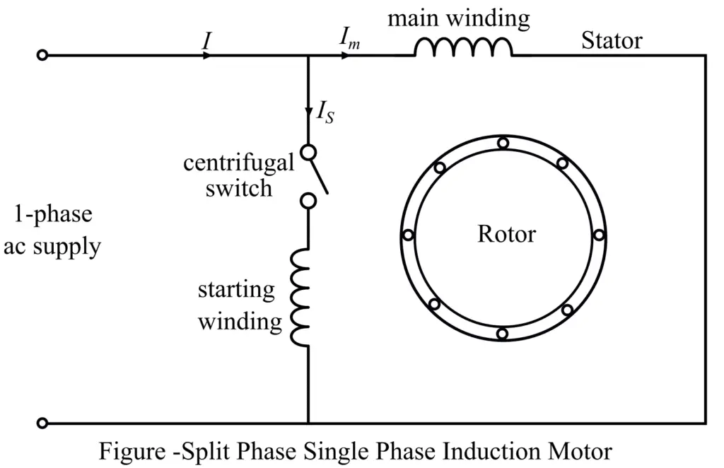
When a single-phase AC supply is fed to the motor, then a current IS flows through the starting winding, while a current Im flows through the main winding. Since, the starting winding has high resistance and low inductance, while the main winding has high inductance and low resistance. As a result, there is a significant phase difference of about 25° to 30° between the starting winding current (IS) and the main winding current (Im). Consequently, a weak rotating magnetic field is produced in the motor which causes the production of self-starting torque in the motor. This starting torque in the split phase induction motor is given by,
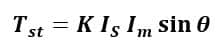
Where K is the proportionality constant that depends on the design specification of the motor.
Once the motor attains about 80% of the rated speed, the centrifugal switch removes the starting winding from the motor circuit. Now, the motor runs as a single-phase induction motor and attains the normal rated speed.
The split phase induction motor draws a very large starting current, around 7 to 8 times of rated current. The torque developed by the split phase motor at starting is about 1.5 times of the rated torque. The split phase induction motors are inexpensive and hence these are very popular in the market with power ratings of about 60 W to 250 W.
The common applications of split phase induction motors are in fans, washing machines, blowers, mixer & grinders, machine tools, etc.
Capacitor Start Induction Motor
The type of single-phase induction motor in which starting torque is produced by using an assembly of a starting capacitor and auxiliary winding is called a capacitor start induction motor.
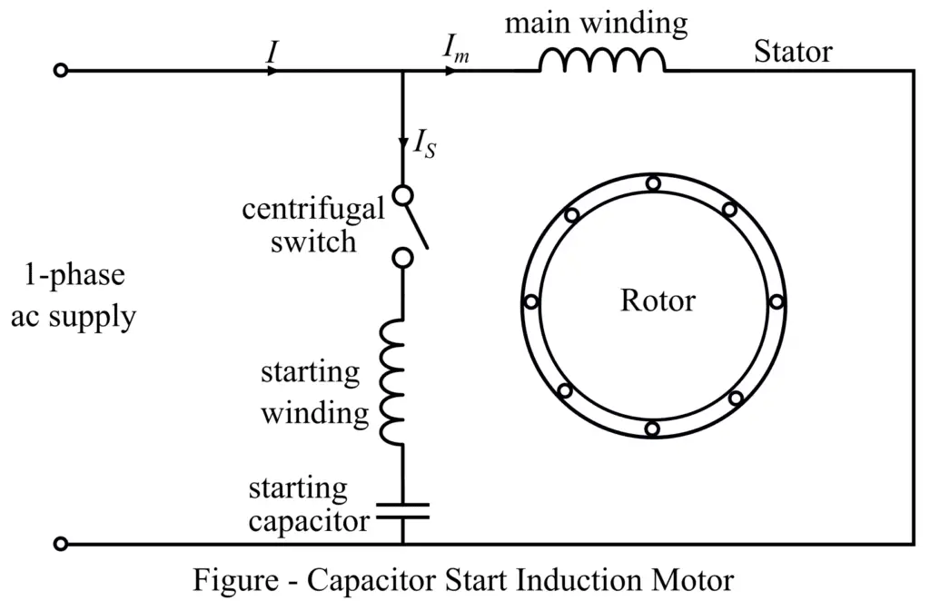
The circuit diagram of a typical capacitor start single-phase induction motor is shown in the figure. It consists of an auxiliary winding (or starting winding) and a running winding (or main winding). In this motor circuit, the starting capacitor is connected in series with the starting winding.
The starting capacitor introduces a phase difference of 90° between the starting winding current (IS) and the main winding current (Im). The starting torque of the capacitor start induction motor is given by,
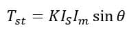
In the case of the capacitor start induction motor, the value of the phase angle is high (90°). Hence from the starting torque equation, it is clear that These motors have very high starting torque.
In this type of motor, a centrifugal switch is used to isolate the starting winding and capacitor from the motor circuit as the speed of the motor becomes around 75% of the rated speed. After that, the motor runs as a single-phase induction motor and accelerates to attain the normal rated speed.
The starting torque developed in the capacitor start induction motors is about 3 to 4.5 times the full load torque. These motors are widely used for driving pumps, compressors, AC and refrigerator compressors, conveyors, and other mechanical loads of high inertia.
Capacitor Start Capacitor Run Motor
The capacitor-start capacitor-run motor is also a type of single-phase induction motor in which two capacitors are used for its operation, one is for starting the motor and another is for running the motor. Therefore, based on the function, these capacitors are named the starting and running capacitors. The circuit diagram of the capacitor-start capacitor run motor is shown in the following figure.
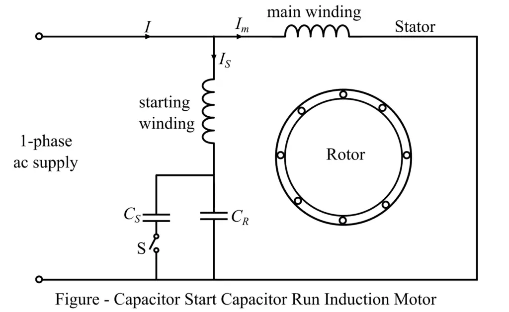
Just like any other type of induction motor, the capacitor-start capacitor-run motor also consists of two major parts namely the stator and rotor. The stator of the capacitor-start capacitor-run motor carries two windings namely auxiliary winding and main winding. These two winding are displaced by 90° in space. The rotor of this motor is a squirrel cage rotor.
The starting capacitor and the running capacitor both are connected in parallel in the motor circuit. Once the motor attains around 75% of the rated speed, the starting capacitor is removed from the circuit with the help of a centrifugal switch, while the running capacitor remains connected in the circuit permanently.
The starting capacitor used is a short-time rated electrolytic capacitor, while the running capacitor is a long-time rated oil-filled paper capacitor. As we have seen that the motor is started with the help of a capacitor and is continuously run by the capacitor as well. That is why it is called a capacitor-start capacitor-run motor.
The operation of the capacitor-start capacitor run motor is quiet and smooth. This type of motor is a highly efficient single-phase induction motor. The most significant advantage of the capacitor-start capacitor-run motor is that it produces a constant torque, instead of pulsating torque, as a result, this motor is free from mechanical vibrations.
The capacitor-start capacitor run motors are most suitable for driving the loads of high inertia that require frequent starting with high efficiency and high pull-out torque. Some common applications are air compressors, refrigerators, hospital equipment, pumps, etc.
Conclusion
Thus, in this article, we discussed all three major types of single-phase induction motors along with their definition, construction and circuit diagram, advantages, and applications. The single-phase AC motors are very popular in domestic and commercial applications such as in home appliances, office appliances, small water pumps, etc.