In this article, we will discuss how we can change the direction of rotation of the induction motor and dc motor. First, we get a basic introduction to an electric motor, induction motor, and dc motor.
An electric motor is an electromechanical energy conversion machine that transforms input electrical energy into output mechanical energy in the form of the rotation of the shaft. There are several types of electric motors such as induction motors, synchronous motors, dc motors, etc.
This article is primarily meant for explaining the concept of the forward and reverse directions of induction motors and dc motors. An induction motor is a type of asynchronous ac motor whose operation is based on the electromagnetic induction between the stator and rotor. On the other hand, a dc motor uses a direct current supply to operate.
Further, the induction motors are divided into categories namely – single phase induction motor and three-phase induction motor. So we will individually discuss the change in direction.
Forward and Reverse Direction of Single-Phase Induction Motor
A typical single-phase induction motor consists of two windings: main winding (or running winding) and starting winding (or auxiliary winding). The single-phase induction motor is not a self-starting motor like a three-phase induction motor. It is because these motors do not have a rotating magnetic field similar to the three-phase induction motors.
Thus, in order to start a single-phase induction motor, we have a starting capacitor in series with the starting winding. This capacitor splits the single-phase supply into a two-phase supply by introducing a phase shift of ideally 90° electrical. Thus, a rotating magnetic field is produced in the single-phase induction motor, which starts it when a single supply is provided at the input terminals.
Therefore, the direction of rotation of a single-phase induction is governed by the starting capacitor. So we can change the direction of a single-phase induction motor just by changing the connections of the starting capacitor.
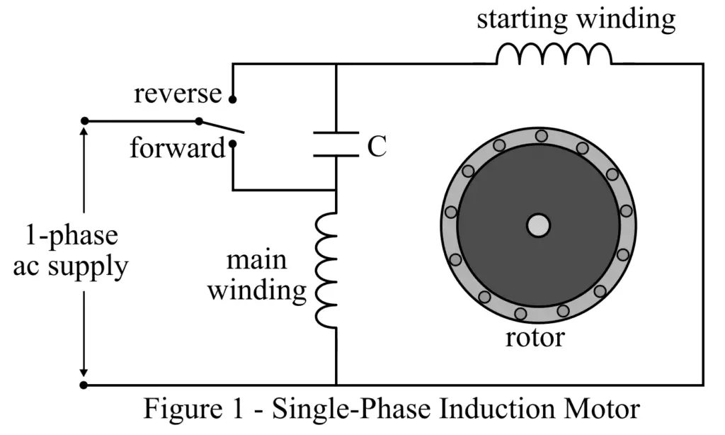
For the forward direction, we connect the starting capacitor in series with the starting (or auxiliary) winding of the motor. While, for the reverse direction, we need to connect the starting capacitor in series with the main (or running) winding instead of starting winding. The connection diagrams of a single-phase induction motor for forward and reverse directions of rotation are shown in figure-1.
Forward and Reverse Direction of Three-Phase Induction Motor
A three-phase induction motor takes a three-phase input electrical supply. Therefore, the three-phase induction motor is a self-starting motor because the three-phase electrical supply can produce a rotating magnetic field in the machine.
Thus, the direction of rotation of the three-phase induction motor is governed by the rotating magnetic field. This means, for reversing the direction of the motor, we need to change the direction of the rotating magnetic field. This is achieved by changing the phase sequence of the three-phase supply.
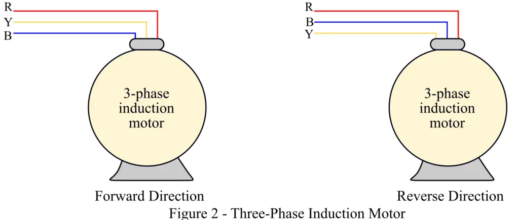
For example – if a three-phase induction motor rotates in the forward direction for the phase-sequence RYB as shown in figure 2. Then, the motor will rotate in the reverse direction for the phase sequence RBY.
Forward and Reverse Direction of DC Motor
A typical DC motor consists of two windings namely – field winding and armature winding. The field winding produces a constant working magnetic field in the machine, while the armature winding produces the working torque to drive the mechanical load.
DC Series Motor
The direction of rotation of a DC series motor can be changed in two ways.
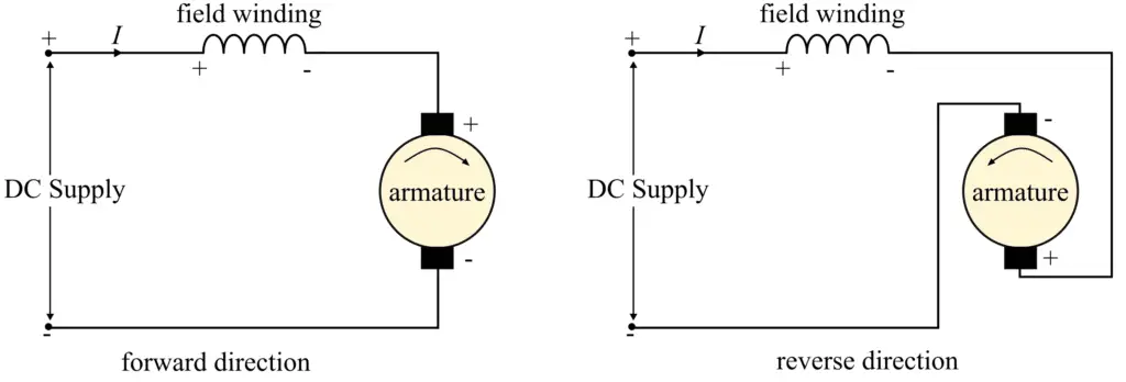
(1). By changing the polarity of armature winding
(2). By changing the polarity of the field winding
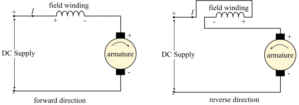
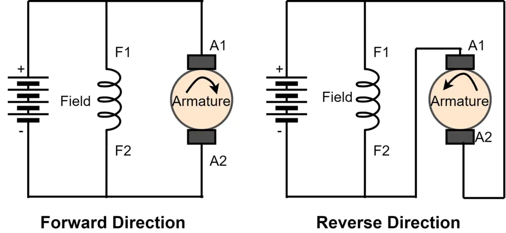
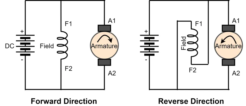
The connection diagram of the forward and reverse directions of the DC motor by changing the polarity of armature winding and by changing the polarity of field current is shown in figure 3 and figure 4 respectively. Never reverse the polarity of both field and armature winding to change the direction of the DC series motor, if we change the polarity of both winding the direction will remain unchanged.
DC Shunt Motor
The direction of rotation of a DC shunt motor can be changed in two ways.
(1). By changing the polarity of the Armature winding
(2). By changing the polarity of the field winding
Separately Excited DC Shunt Motor
The direction of rotation of a separately excited DC shunt motor can be changed in two ways.
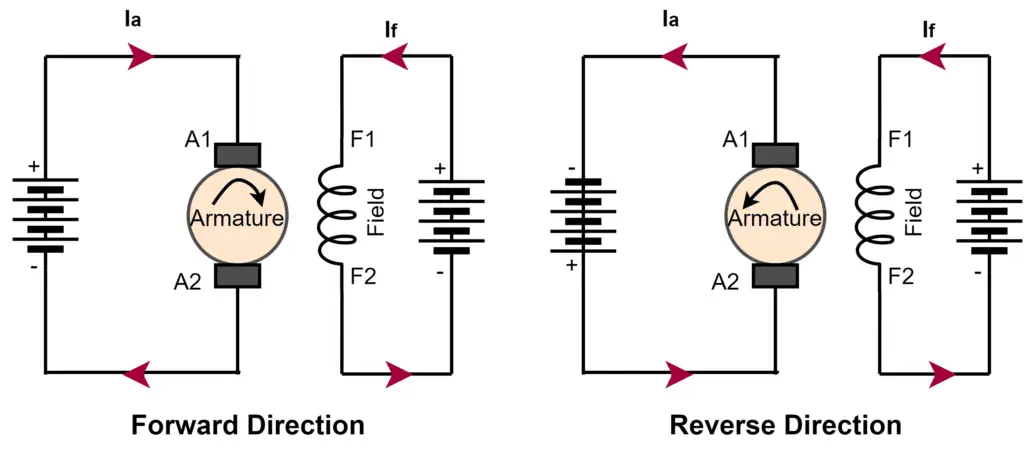
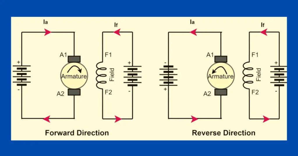
(1). By changing the direction of the Armature Current
The direction of the armature current can be changed by changing the polarity of the DC supply at the armature terminals of a separately excited DC motor. With the change in the direction of the armature current, the direction of rotation of the motor changes.
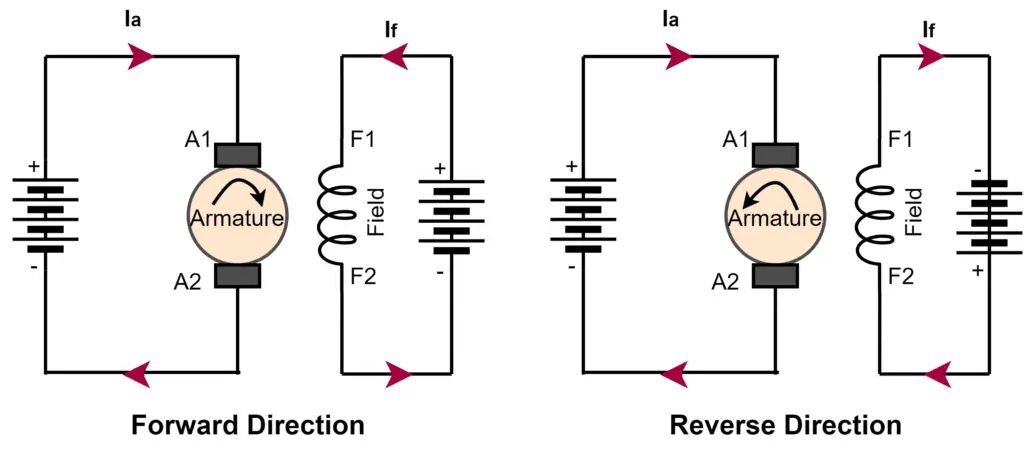
(1). By changing the direction of the Field Current
The direction of the field current can be changed by changing the polarity of the DC supply at the field terminals of a separately excited DC motor. With the change in the direction of the field current, the direction of rotation of the motor changes.
Summary
Now, we can conclude this article with the following points-
- The direction of rotation of a single-phase induction motor is changed by changing the connection of the capacitor with the auxiliary winding or main winding.
- The direction of rotation of a three-phase induction motor is changed by changing the phase sequence of the input three-phase supply.
- The direction of rotation of a separately excited DC motor can be changed by changing the direction of either field current or armature current.
- The direction of the DC series motor can be changed by either changing the polarity of field winding or armature winding.
- The direction of the DC shunt motor can be changed by either changing the polarity of field winding or armature winding.
Related Articles:
thanks , i have a question, in case of reverse do we need a run capacitor ?