In this post, we will discuss the braking theory in VFD. The braking is an important part of motoring. There are many processes that require braking after forward and reverse motoring.
The opposite force applied to stop the moving equipment is called braking. If the motor is moving in the clockwise direction, the brake applies in the anti-clockwise direction to stop the motor.
The variable-frequency drive is the most popular drive nowadays. It is suitable for most applications. The VFD can drive the induction motor in the forward as well as in the reverse direction.
Apart from motoring, the VFD can brake the running motor. Thus, the VFD is the powerful controller which can control the speed of the motor & apply the brake whenever required.
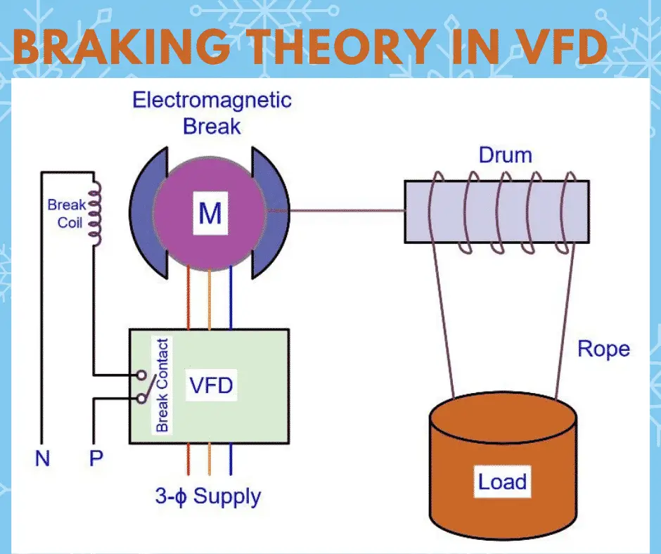
Braking Theory in VFD
Let us understand how the VFD braking theory applies to braking in the hoisting systems.
We use the hoisting system for lowering and lifting the loads. You might have seen the hoists at the construction sites and factories.
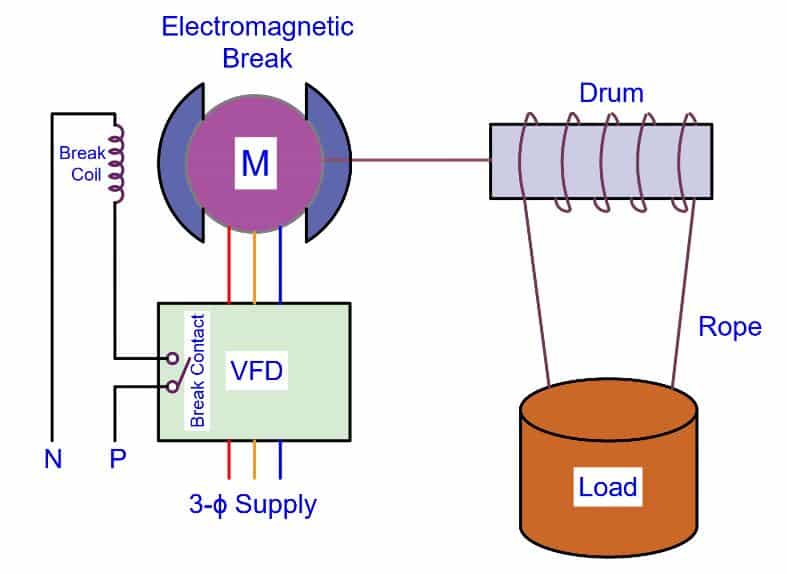
The hoisting system has the following parts,
- Induction motor
- Drum
- Wire rope
- Hook Block
- Pendent switch
- Electromagnetic brake
How does VFD Controls Hoist Motor & Brake?
The VFD rotates the drum. The ropes attached to the drum start moving up and down causing the load to raise or lower.
Take a case of lowering the load. During lowering of the load, the gravitational force also applies on the downward side. If we stop the motor during lowering of the load, the gravitation force tends to rotate the motor. Here, the opposite force stops the motor.
The motor without a brake for this application may cause damage to equipment & may cause accidents as well. Moreover, this is not a safe practice.
When we stop the motor during the lowering of the load, the VFD issues a command to the electromagnetic brake. The brake holds the drum and thus, braking applies.
The above unsafe practice needs proper attention. One of the methods to eradicate the problem is the use of an electromagnetic brake along with the mechanical brake. The brake may be applied to the drum by the movement of the liners towards the drum. This can be easily done by an electromagnetic brake.
Control Mechanism of VFD and Brake
The liner holds the drum during the motor stop. When we give the start command to the motor, first the electromagnet receives the supply and drum brake release. Immediately after releasing of brake motor starts rotating.
When we stop the motor, the potential energy stored in the spring releases, and the friction disk(liner) holds the drum. In this way, braking applies to an induction motor.
We use a power contactor for the implementation of the control scheme. We mount a contactor in the VFD panel. As per the VFD programming of the brake system, the brake applies and brake releases.
The maloperation of brake logic may cause severe damage to equipment and the person operating the hoist.
The reliability of the brake logic is a must to avoid any damage to machines and personnel.
Important Parameters of braking in VFD
Understanding VFD parameters for brake logic in VFD is very important. The most important VFD parameters are as follows.
Brake Release Start Frequency
The brake release start frequency is the minimum frequency that VFD outputs to provide sufficient torque to hold the load without movement. This parameter can be calculated by the slip speed and the required holding torque.
At this frequency, the holding torque is equal to the static torque of the load.
After the lapse of the specified time, the VFD starts ramping up the motor.
Brake Engage Start Frequency
The brake engages start frequency defines the required frequency that the VFD outputs to the motor to provide sufficient torque to hold the load without movement.
This is the frequency at which the motor will run when brakes are engaged. It runs only for a specified time after ramp-down has started and reached this frequency. After this, VFD will move to zero frequency.
Brake Engage Delay Time
This is the delay after that brake engages. This time permits the system to manage any dynamic effect during stopping.
Brake Engage Closing time
The time taken to fully engage the drum after removing the coil supply of the brake is the brake engage closing time. In the brake engage closing time the brake exerts the full torque on the drum. The brake engages closing time can be set in the VFD.
VFD Ramp up time (Brake release time)
The time for which the motor runs at brake release frequency with brakes released. After the lapse of this time, the VFD accelerates the motor according to set VFD ramp up time.
Brake Logic Output
One digital output is assigned for the opening and closing of the brake contactor in the VFD panel.
Brake Engage Fade out Time.
Fade-out time starts after the lapse of brake engage closing time. The motor current is reduced to zero during the brake engage fade-out time. After the lapse of fade-out time, the modulation remains on for another 100 milliseconds.
After understanding all the braking terminology in VFD, now let us understand the logical sequence of the braking system.
Logic Sequence of Braking in VFD
The logic sequence of braking in VFD is given below.
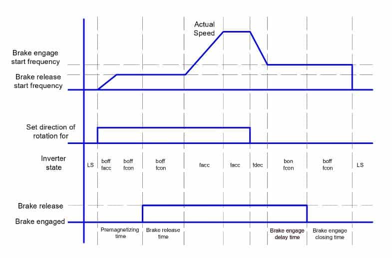
Now, let us look at the flow of the logic sequence.
- VFD receives the start command. The VFD speeds up the motor as per set ramp up time. The motor achieves the speed up to brake release frequency.
- After motor reaching at the brake release frequency, VFD issues a stop command to the magnetic contactor to release the brake.
- Now, after releasing of the brake, the VFD gives output to motor in a ramp-up manner. The motor speeds up to the set frequency.
- When the sop command is given to motor, the motor first decelerate up to the brake engage frequency.
- After reaching at brake engage frequency, the brake engage delay starts.
- After lapse of the brake engage delay, the VFD issues a start command command to the magnetic contactor. The brake coil energizes and the brake applies. note that at this time motor is running at the brake engage frequency,
- After lapse of brake engage time, the VFD reduces its frequency towards zero.
Read Next: