The main difference between contactor vs relay is their typical application and switching capability. A contactor is primarily designed for switching electrical power to motors, heaters, lighting systems, and other relatively high-power loads, while a relay is generally used for control, signaling, switching, and protection circuits involving lower power levels.
Both contactors and relays are electrically operated switching devices. They use an electromagnetic mechanism or another actuating mechanism to open or close electrical contacts. However, their construction, contact arrangement, switching capacity, application, and protection features can differ significantly.
Understanding contactor vs relay is important when selecting a switching device because the wrong device can result in contact damage, excessive heating, arcing, unreliable operation, or reduced service life.
Contactor vs Relay Comparison Table
The following table highlights the major differences between contactor vs relay.
| Feature | Contactor | Relay |
| Primary purpose | Switching power loads | Switching control, signal, and relatively low-power circuits |
| Typical application | Motors, heaters, compressors, lighting | Control circuits, automation, protection, signaling |
| Load switching | Generally designed for higher-power loads | Generally designed for lower-power loads |
| Number of power contacts | Commonly 2, 3, or 4 main contacts | Contact arrangements vary widely |
| Auxiliary contacts | Commonly provided for control and interlocking | NO and NC contacts are commonly available |
| Contact arrangement | Main contacts plus auxiliary contacts | NO, NC, changeover and other configurations |
| Arc management | Designed with features suitable for higher-current switching | Depends on relay design and contact rating |
| Physical size | Generally larger for equivalent high-current applications | Generally smaller |
| Typical control voltage | Available in many AC and DC coil ratings | Available in many AC and DC coil ratings |
| Application voltage | Available for a wide range of power-system voltages | Available for a wide range of control and switching voltages |
| Motor switching | Commonly used | Generally used for control rather than direct motor power switching |
| Electrical interlocking | Commonly used | Also possible |
| Overload protection | Normally used with separate overload protection | Normally used with separate protection as required |
| Common applications | Motors, pumps, compressors, heaters, lighting | Automation, PLC interfaces, alarms, control and signaling |
| Main advantage | Suitable for frequent switching of power loads | Versatile switching and control |
| Main limitation | Larger and generally more expensive for simple control tasks | Not normally intended for high-power load switching |
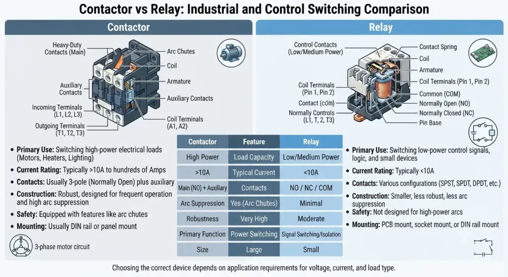
What Is a Contactor?
A contactor is an electrically operated switching device used mainly to establish or interrupt power to electrical loads. Contactors are widely used in motor control circuits, industrial control panels, HVAC equipment, compressors, pumps, heating systems, and lighting installations.
A contactor normally consists of an electromagnetic coil, magnetic core, armature, main contacts, auxiliary contacts, and mechanical return arrangement. When the coil is energized, the magnetic field attracts the armature and changes the state of the contacts.
When the coil is de-energized, the electromagnetic force disappears and the contacts return to their normal position.
Characteristics of a Contactor
Important characteristics of contactors include:
- Designed primarily for switching electrical power loads.
- Commonly used for AC motor control.
- Available with two, three, four, or other numbers of main poles depending on the application.
- Main contacts are designed to carry the load current.
- Auxiliary contacts are available for control and signaling functions.
- Normally open and normally closed auxiliary contacts can be used in control circuits.
- Available with AC or DC operating coils.
- Designed for frequent switching operations according to their specified utilization category.
- Include mechanical arrangements that ensure contacts return when the coil is de-energized.
- May incorporate or be used with arc-control features appropriate to the switching duty.
- Can be integrated with overload relays, circuit breakers, fuses, and other protection devices.
Uses of Contactors
Contactors are commonly used in electrical power and industrial control systems.
Common applications include:
- Three-phase induction motor control.
- Pumps.
- Compressors.
- Fans and blowers.
- HVAC systems.
- Electric heaters.
- Industrial machinery.
- Conveyor systems.
- Lighting control.
- Capacitor switching applications using appropriately rated devices.
- Power distribution and control panels.
- Star-delta motor starters.
- Direct-on-line motor starters.
- Automatic motor control systems.
A contactor is generally selected when the switching device must repeatedly establish or interrupt power to a load rather than simply switch a control or signal circuit.
What Is a Relay?
A relay is an electrically operated switching device used to control one electrical circuit using a signal from another circuit. Relays are widely used in control systems, automation, protection, instrumentation, signaling, and electrical equipment.
An electromagnetic relay typically contains a coil, magnetic circuit, armature, and contacts. When current flows through the coil, a magnetic field is produced. The magnetic force moves the armature and changes the state of the contacts.
Depending on the relay design, the contacts may be normally open (NO), normally closed (NC), or changeover contacts.
Characteristics of a Relay
Important characteristics of relays include:
- Used extensively in control and automation circuits.
- Can provide electrical isolation between control and switched circuits.
- Available with NO, NC, and changeover contact arrangements.
- Available with AC and DC coils.
- Available in electromechanical and solid-state forms.
- Different relay designs are available for different voltage and current ratings.
- Used for control, signaling, protection, and switching.
- Can interface low-power control signals with other electrical circuits.
- Available in compact packages for electronic and industrial applications.
- Contact ratings vary according to relay design and manufacturer specifications.
Uses of Relays
Relays are used in many electrical, electronic, and automation applications.
Common applications include:
- Control circuits.
- PLC interface circuits.
- Alarm systems.
- Protection circuits.
- Electrical interlocking.
- Instrumentation.
- Automation systems.
- Signaling circuits.
- Lighting control.
- Automotive electrical systems.
- Industrial control panels.
- Switching auxiliary loads.
- Monitoring systems.
A relay is particularly useful when a control signal needs to operate another circuit while providing suitable electrical isolation between the two circuits.
Contactor vs Relay: Key Differences
1. Application
The most important difference between a contactor and relay is their typical application.
A contactor is primarily used to switch electrical power supplied to loads such as motors, pumps, compressors, heaters, and other industrial equipment.
A relay is generally used for control, signaling, automation, protection, and switching relatively lower-power circuits.
However, the distinction is based on typical design and application rather than a single current value. Some relays can switch substantial loads, while some contactors are designed for relatively modest loads.
2. Symbol
The symbol used for a relay depends on its contact arrangement, such as normally open (NO), normally closed (NC), or changeover (SPDT) contacts. A relay symbol generally shows the operating coil and the contacts controlled by that coil.
A contactor is similarly represented by its operating coil and switching contacts. In power and motor-control diagrams, the main contacts are normally shown separately from auxiliary contacts so that the power circuit and control circuit can be clearly identified.
The exact graphical representation can vary according to the applicable electrical drawing standard and the type of device. Therefore, the device designation, contact labels, and circuit diagram should be considered together when identifying a relay or contactor.
Relay Symbol
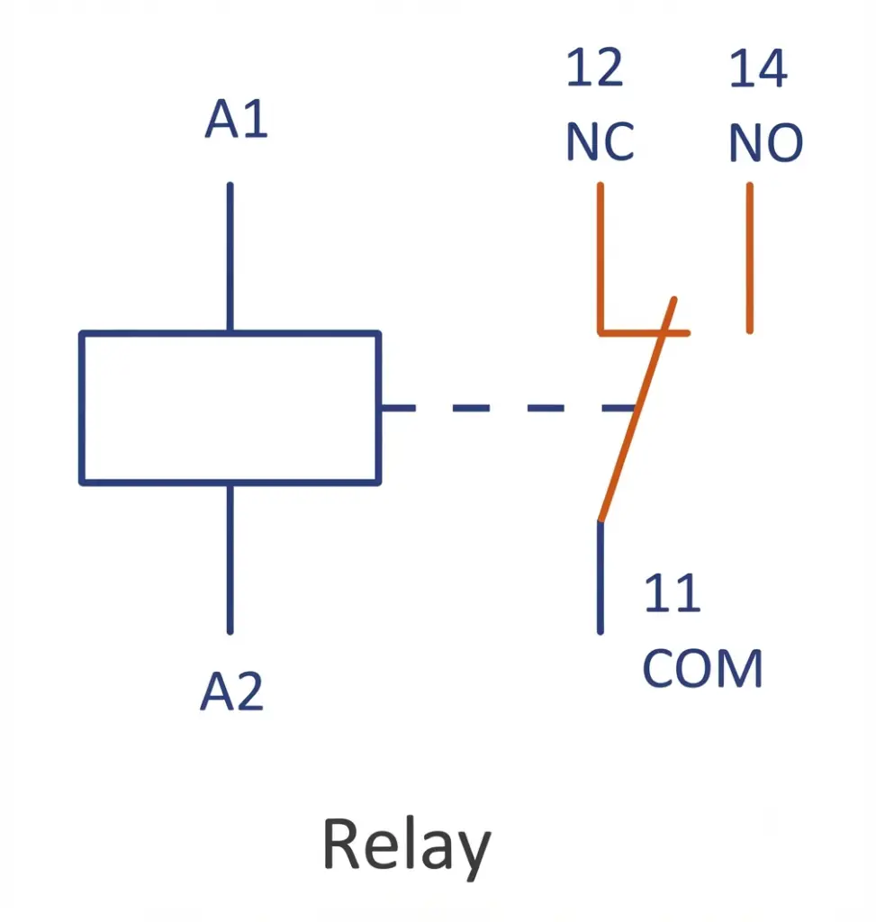
A relay symbol typically represents the coil and its associated switching contacts. Depending on the relay configuration, the diagram may show NO, NC, or changeover contacts.
Contactor Symbol
A contactor symbol represents the contactor coil and its main or auxiliary contacts. In motor-control diagrams, the main contacts are generally shown in the power circuit, while auxiliary contacts may appear in the control circuit.
Understanding these symbols makes it easier to follow electrical schematics and identify how a relay or contactor controls a load.
3. Load Capacity
The load-carrying capacity is one of the important differences between a contactor and a relay. In typical applications, contactors are designed to handle higher electrical loads than conventional control relays. However, the actual capacity depends on the specific device and its manufacturer’s ratings.
Both contactors and relays can have ratings for:
- Voltage
- Current (ampere)
- Load or horsepower, where applicable
Contactors used for motor and power switching are generally available with higher current and load ratings than typical control relays. Relays, on the other hand, are commonly used for control, signaling, and relatively lower-power loads, although specialized power relays can also handle higher currents.
The voltage rating also varies considerably between devices. A control relay may be rated for a few hundred volts, while contactors are available for higher-voltage power applications. Therefore, there is no single voltage, current, or horsepower value that universally separates a relay from a contactor.
For motor applications, the contactor should be selected according to the motor’s rated current, starting conditions, voltage, load type, utilization category, and required switching duty. The relay should likewise be selected according to the actual load and its specified contact rating.
| Rating | Contactor | Relay |
| Current rating | Generally higher for power-load switching | Generally lower for conventional control applications |
| Voltage rating | Available for a wide range of power-system voltages | Available for a wide range of control and switching voltages |
| Horsepower rating | Commonly specified for motor applications | Specified for applicable load types and relay designs |
| Typical use | Motors and other power loads | Control, signaling, automation, and lower-power loads |
4. AC and DC Loads
The suitability of a contactor or relay for an AC or DC load depends on the device’s contact design and specified ratings. AC and DC loads behave differently when their circuits are interrupted, so the switching device must be rated for the particular type of current.
Contactors are widely used for AC power switching, particularly in motor-control applications. AC contactors are designed with contact systems and arc-control arrangements appropriate for their specified AC switching duty.
DC switching can be more demanding because a DC arc does not naturally pass through a zero-current point as an AC arc does. As a result, a device intended for AC switching may have a significantly different DC contact rating. Some contactors are specifically designed and rated for DC applications and can be used when their DC voltage and current ratings are suitable.
Relays are available for both AC and DC switching applications. However, a relay suitable for an AC load should not automatically be assumed to have the same rating for a DC load.
Therefore, the important consideration is not simply whether the device is called a relay or contactor. The AC or DC nature of the load, voltage, current, load type, and manufacturer’s contact rating must all be considered.
5. Single-Phase and Multi-Phase Loads
Contactors are commonly used for both single-phase and three-phase circuits, with three-pole contactors being particularly common in industrial motor-control applications. A three-phase contactor can switch the three supply phases using its main contacts.
Relays are also available with different numbers of contacts and can be used for single-phase circuits as well as for applications where multiple circuits must be switched. However, a conventional control relay may not be suitable for directly switching a three-phase power load.
When a multi-phase load needs to be switched, the device must have an appropriate number of independently rated contacts and must be suitable for the voltage, current, load type, and switching duty of each phase.
For example, a three-phase motor circuit commonly uses a three-pole contactor, while relays may be used in the associated control circuit to provide commands, interlocking, monitoring, or signaling.
Thus, contactors are particularly common for multi-phase power switching, while relays are widely used for control and switching functions.
6. NO and NC Contacts
Both relays and contactors can use normally open (NO) and normally closed (NC) contacts, depending on their design.
A Normally Open (NO) contact remains open when the operating coil is de-energized. When the coil is energized, the contact closes and allows current to flow through the switched circuit.
A Normally Closed (NC) contact remains closed when the coil is de-energized. When the coil is energized, the contact opens and interrupts the circuit.
These contact arrangements are important in control and automation circuits.
For example, an NO auxiliary contact of a contactor can be used in a self-holding or sealing circuit, while an NC contact can be used for electrical interlocking or status indication.
Relays may also provide NO, NC, or changeover contacts for control, signaling, automation, and switching applications.
The key difference is therefore not whether the device has NO or NC contacts, because both relays and contactors can provide them. The important consideration is the contact’s electrical rating and its intended function in the circuit.
7. Current Switching Capacity
Contactors are generally designed to switch higher currents than control relays. Their main contacts are constructed to carry the rated load current and withstand the electrical and mechanical stresses associated with repeated switching.
Relays are available in a wide range of contact ratings. Many are intended for control and signal circuits, while specialized power relays can switch considerably higher currents.
Therefore, current rating should always be checked from the manufacturer’s specifications rather than assuming a fixed current limit for every relay or contactor.
8. Physical Size
Contactors are generally larger than relays when designed for comparable switching duties because their construction must accommodate power contacts, insulation, mechanical clearances, and appropriate arc-management arrangements.
Relays are often smaller because many are designed for control, signaling, or lower-power switching applications.
However, physical size is not a reliable way to identify a device’s electrical rating. The datasheet and nameplate ratings should always be used.
9. Number and Type of Contacts
A contactor commonly has main power contacts for switching the load and may also have auxiliary contacts for control and signaling.
For example, a three-phase motor contactor commonly has three main poles for the three phases. Additional auxiliary contacts can be used for holding circuits, electrical interlocking, indication, and control logic.
Relays can have different contact configurations, including:
- Normally Open (NO)
- Normally Closed (NC)
- Changeover contacts
- Single-pole configurations
- Multiple contact sets
The exact arrangement depends on the relay design.
10. Motor Switching
Contactors are commonly used to switch motors because motors can draw substantial current during starting and can generate significant electrical arcing when their circuits are interrupted.
A motor starter may use a contactor together with an overload relay or electronic overload protection device.
A conventional control relay is generally used to control the contactor coil rather than directly switching the motor’s power circuit.
For example, a relay or PLC output can energize a contactor coil, while the contactor main contacts connect the motor to the power supply.
11. Arc Suppression and Arc Management
An electrical arc can form when contacts separate while current is flowing, particularly when switching inductive or high-power loads.
Contactors intended for power switching are designed with contact systems and arc-control features appropriate to their rated switching duty. Their design helps control the effects of arcing during repeated switching operations.
Relays can also experience contact arcing. Depending on their design and application, they may use contact materials, magnetic blowout arrangements, protective circuits, or other methods to manage switching arcs.
Therefore, it is incorrect to assume that relays never require arc suppression. The required method depends on the relay type, switched load, voltage, current, and switching frequency.
12. Auxiliary Contacts
Auxiliary contacts are an important feature of many contactors.
They are normally used in control circuits rather than for carrying the main load current. Auxiliary contacts can be used for:
- Self-holding circuits.
- Electrical interlocking.
- Contactor status indication.
- Control logic.
- Alarm circuits.
- Sequence control.
Relays also provide contacts for control and switching functions, but their contact arrangement depends on the particular relay.
13. Voltage Rating
There is no single voltage rating that applies to every relay or contactor.
Both devices are manufactured for different control and load voltages. A contactor may be designed for switching low-voltage control loads or higher-voltage power circuits, depending on its construction and rating.
Similarly, relays are available with different contact voltage ratings.
The coil voltage and contact/load voltage are separate specifications. A contactor or relay may have a 24 VDC, 24 VAC, 110 VAC, 230 VAC, or other coil rating while its contacts are rated for a different circuit voltage.
The correct voltage must therefore be selected from the device’s datasheet.
14. Coil and Operating Mechanism
Both electromagnetic contactors and electromagnetic relays use a coil to produce a magnetic field.
When the coil is energized, the magnetic field moves an armature. This movement changes the state of the electrical contacts.
When the coil is de-energized, a spring or another return mechanism moves the contacts back to their normal state.
The basic electromagnetic operating principle is therefore similar, although the mechanical construction and switching duty can be very different.
15. Spring-Loaded Contacts
A contactor generally uses a mechanical return arrangement to ensure that the main contacts move to their normal position when the coil is de-energized.
Relays also commonly use springs or other mechanisms to return their contacts to the normal position.
Therefore, spring-loaded or spring-return contacts are not an exclusive feature of contactors. The exact mechanism depends on the device design.
The return mechanism is important because it determines the normal state of the contacts and ensures reliable switching when the operating coil is de-energized.
16. Switching Frequency and Duty
Contactors are designed for switching duties specified by their manufacturers and relevant standards. Motor contactors, for example, may be selected according to utilization categories that account for the type of load and switching duty.
Relays are also available for different switching frequencies and electrical loads.
When selecting either device, the number of operations, load type, starting current, breaking current, electrical life, and mechanical life should be considered.
A device that is suitable for occasional switching may not be suitable for frequent switching of an inductive load.
17. Protection and Overload Coordination
A contactor itself does not normally provide complete overload or short-circuit protection for the connected load.
For motor applications, the contactor is commonly combined with an overload relay, motor protection device, fuse, circuit breaker, or other protective equipment.
Relays may also be used as part of protection systems, but the protection function depends on the particular relay type.
For example, an overload relay can detect motor overcurrent and initiate a control action that de-energizes the contactor.
18. Safety Features
Safety is an important consideration when selecting a switching device, particularly when the device is used to control high-current or inductive loads.
When the contacts of a switching device open while current is flowing, an electrical arc can form between the contacts. The intensity of the arc depends on factors such as circuit voltage, load current, load characteristics, and the type of current being switched.
Contactors designed for power switching incorporate contact systems and arc-control arrangements appropriate to their rated switching duty. Depending on the contactor design, these may include arc chutes, arc barriers, magnetic blowout arrangements, or specially designed contact structures that help control and extinguish the arc.
Relays can also experience contact arcing when switching electrical loads. Because many control relays are used for relatively lower-power circuits, the energy involved in contact interruption may be lower than in a comparable high-power contactor application. However, the relay’s specified contact rating and load category must always be observed.
Additional protection may also be required when switching inductive loads. Devices such as RC snubbers, flyback diodes, varistors, or other suppression circuits can be used where appropriate to reduce voltage transients and contact stress.
Therefore, the safety of a contactor or relay depends not only on the device type but also on its voltage and current rating, load characteristics, switching duty, arc-control design, protection circuitry, and correct installation.
Contactor vs Relay: Which One Should You Use?
There is no universal answer because the correct choice depends on the electrical load and switching requirements.
A contactor is generally appropriate when the application requires:
- Switching motors or other power loads.
- Frequent switching of a rated power circuit.
- Three-phase load switching.
- Main power contacts.
- Auxiliary contacts for motor-control logic.
- Integration with overload and motor-protection systems.
- Industrial power control.
A relay is generally appropriate when the application requires:
- Control signal switching.
- Electrical isolation between circuits.
- PLC interfacing.
- Signaling or alarm functions.
- Control logic.
- Instrumentation.
- Switching relatively low-power loads.
- Compact switching devices.
The final selection should always be based on the actual voltage, current, load type, switching frequency, electrical life, control voltage, contact configuration, and manufacturer’s ratings.
Similarities Between Contactor and Relay
Although contactors and relays have different typical applications, they have several similarities.
Important similarities include:
- Both are switching devices.
- Both can be electrically operated.
- Electromagnetic versions use a coil and magnetic mechanism.
- Both can have normally open (NO) and normally closed (NC) contacts.
- Both can be used in control circuits.
- Both can provide electrical isolation between control and switched circuits, depending on their construction.
- Both are available with AC and DC operating coils.
- Both can be used for automation and electrical control.
- Both have specified electrical and mechanical life.
- Both require proper selection according to the load and switching duty.
How to Select Between a Contactor and Relay
The selection should be based on the actual requirements of the circuit rather than simply choosing a device based on its physical size.
Consider the following factors:
1. Load Current
Determine the normal operating current and, where applicable, starting or inrush current.
2. Load Voltage
Check the voltage that the contacts must switch. The contact rating must be suitable for the actual circuit voltage.
3. Load Type
Resistive, inductive, capacitive, motor, lamp, and electronic loads can place different stresses on switching contacts.
4. Switching Frequency
Determine how frequently the device will operate. Frequent switching can affect contact wear and electrical life.
5. Control Voltage
Select a coil that matches the available control voltage, such as 24 VDC, 24 VAC, 110 VAC, or 230 VAC, as applicable.
6. Contact Configuration
Check whether the circuit requires NO, NC, changeover, main power, or auxiliary contacts.
7. Electrical Life
The expected number of switching operations should be compared with the device’s specified electrical life for the actual load.
8. Protection and Coordination
For motor applications, consider coordination with overload relays, circuit breakers, fuses, and other protective devices.
9. Installation Environment
Temperature, humidity, dust, vibration, enclosure conditions, and other environmental factors can affect device performance.
10. Standards and Utilization Category
For industrial applications, the applicable standards and utilization category should be considered when selecting a contactor or relay.
Conclusion
The comparison of contactor vs relay shows that both devices perform electrical switching but are generally designed for different applications.
A contactor is commonly used to switch motors, pumps, compressors, heaters, lighting systems, and other power loads. It typically has main power contacts and may include auxiliary contacts for control and interlocking.
A relay is commonly used in control, automation, instrumentation, protection, signaling, and switching applications. Relays are available in many contact configurations and ratings, including specialized types for higher-power applications.
The key difference is therefore not simply a fixed current rating or physical size. The appropriate device depends on the load current, voltage, load type, switching frequency, contact configuration, control voltage, electrical life, and application requirements.
For motor and industrial power switching, a suitably rated contactor is commonly used. For control, signaling, automation, and lower-power switching, a suitably rated relay is often used.
Frequently Asked Questions
The main difference is their typical application. A contactor is primarily designed for switching electrical power loads, particularly motors and other industrial loads, while a relay is commonly used for control, signaling, automation, protection, and lower-power switching applications.
A contactor and relay are both electrically operated switching devices, and electromagnetic versions use similar operating principles. However, contactors are specifically designed and rated for particular power-switching duties, while relays cover a much broader range of control and switching applications.
Neither is universally better. A contactor is generally suitable for power-load switching, while a relay is generally suitable for control and signaling applications. The correct choice depends on the load, voltage, current, switching duty, and device ratings.
A relay can replace a contactor only when its contact ratings and switching capability are suitable for the actual load and duty. A conventional control relay should not be used to switch a load that exceeds its specified contact rating.
A suitably rated contactor can perform switching functions, but it may be unnecessarily large or costly for a simple control circuit. The device should be selected according to the required contact configuration, load, switching frequency, and application.
Read Next:
- AC Hum & Contact bounce in Magnetic Contactor?
- Star Delta Starter | Working Principle, Power and Control Circuit Diagram
- Classic Control Basics
- Basic Concepts of the Safety Relay
- PRD of Transformer|Pressure Relief Device for Transformer
- What is Smart or Intelligent MCC? Its Advantages
- Magnetic Contactor: Working Principle, Types, Parts, Advantages & Applications