A short circuit study is an evaluation of an electrical system’s capacity to determine the magnitude of currents that can flow through the electrical network and electrical equipment during an electrical fault.
The short circuit studies are carried out exhaustively with careful design considerations to maintain a very high level of continuity of service, as well as to ensure that the system will be operating as designed. But in the very complexity despite all the efforts, we cannot eliminate the unavoidable situations or conditions that result in a short circuit. Therefore, short circuit analysis of any Power System is important.
So basically, we can define a Short circuit Study as the analysis or evaluation of an electrical power system to determine the magnitude of currents that can flow during an electrical fault and those values can be compared to the ratings of installed equipment and short circuit protection devices.
It is activities related to design considerations for new systems, analytical studies for existing systems, and also addresses operational and model validation considerations for industrial and commercial power systems. There is some popular software available in the industry to study short circuit fault study and analysis such as ETAP, DigSilent, SKM, EasyPower, etc.
Definition of Short Circuit as Per IEC
Definition of short circuit its self, according to IEC 60909 standard, is accidental or intentional conductive path between two or more conductive parts (e.g. three- phase short circuit) forcing the electric potential differences between these conductive parts to be equal or close to zero.
When two nodes of an electric circuit which have different voltages touch each other creates a short circuit fault.
General Causes of Short Circuit
- Faulty wire insulation – Wiring insulation deteriorates and wears off over time which leads the metal leads and copper wires to exposure.
- High levels of temperature due to over-current or overload
- Direct contact connection with live conductors
- Loose electrical connections can increase the likelihood of metal contacts coming in contact with each other.
- Arc caused by condensation together with air, especially in insulators
- The release of electric energy due to excess voltage
- Excess temperature due to over-current or overload
A faulted or short-circuited state can be distinguished generally by a sudden and significant rise in current. The system is subjected to high current and high levels of stress due to this high current. Usually, it is the utility transmission systems, generators, and synchronous and induction motors that supply the short circuit current.
There are two types of Short circuits which are:
- Symmetrical Short circuit – Usually, it happens in all three conductors with short currents simultaneously. 3 phase short circuit events comprise only 5% of total short circuit events. Symmetry type short circuit events occur only for 3-phase systems with or without ground.
- Asymmetrical Short circuit – This type of short circuit occurs in both single and three-phase systems. This type of short circuit happens between current conductors with or without ground. Asymmetrical short circuits can be further divided into types such as:
- Line-to-Line Fault — Any two phases shorted without ground
- Double line to ground fault — Any two phases connected to the ground.
- Single line to a ground fault — One phase is shorted to the ground.
Why short circuit study Important?
It is not possible to fully prevent the short circuit, however we can attempt to reduce it. The short circuit study is a very important tool for designing electrical system. If equipment design are as per the short circuit study, then the possibility of a short circuit becomes small.
The electrical system have design as per the short circuit study. In the case of short circuit, the protection system isolate the faulty section. And thus a rest of electrical system remain operative.
Reasons for performing short-circuit studies
- The short circuit capacity of the existing network changes with extra installation of electrical equipment. Generally, the fault current capacity of electrical network increase with additional installation. In this scenario, the short circuit study verifies the adequacy of existing interrupting equipment. It helps designer for taking the suitable interrupting capacity of equipment in design.
- The short circuit study is helpful in determining the system protective device settings. The current transformer of protective devices must be able to handle the fault current for a reliable protection system.
- The short circuit tells the effects of the fault currents on various system components. The system components are cables, lines, busways, transformers, and reactors during the time the fault. The short circuit current cause a severe thermal and mechanical stress on system components. Therefore, we should compare the stress with first-cycle withstand capabilities of system equipment.
- Assessment of the effect of different types of short circuits may have on the overall system voltage profile. These studies will identify areas in the system for which faults can result in unacceptably widespread voltage. So, it is possible to install the reactive Var system for system voltage improvements.
- The short circuit study is a good tool for conceptualization, design and refinement of system layout. It also helps in designing a neutral grounding, and substation grounding.
Anatomy of a Short Circuit Current
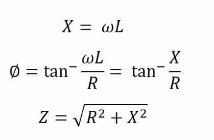
A faulty power system can be represented or simplified into an equivalent circuit with an ideal voltage source, resistance, and inductance connected in series. The figure below simulates a short circuit condition:
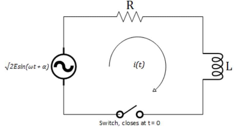
By Kirchoff’s Voltage law,
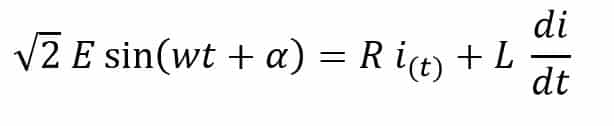
Where,
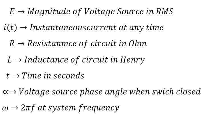
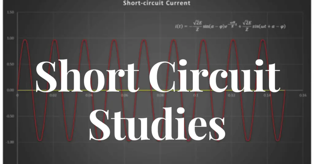
Solving for instantaneous current i(t) we get,
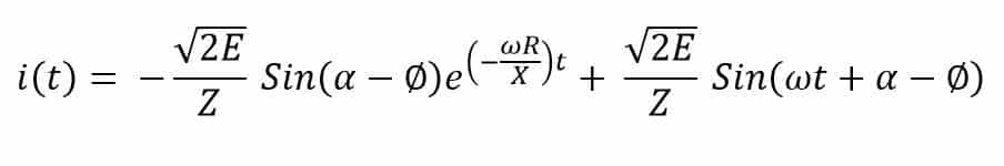
Where,
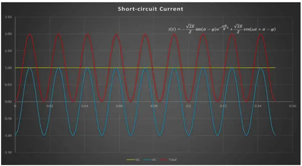
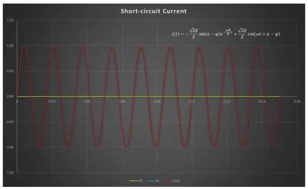
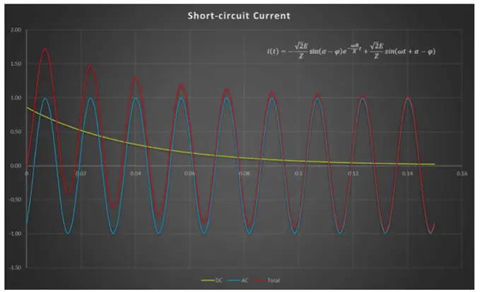
In the above expressions, the instantaneous short circuit current i(t), has two components, the transient dc component, and the steady-state ac component. The steady-state ac component remains symmetrical but the transient dc component exponentially decays based on the X/R ratio due to which the fault current becomes asymmetrical. It is important to note that whenever a fault occurs, the magnitude of the dc and ac components is dependent on the phase angle of the voltage source.
For example, if we consider a purely inductive circuit, the below figure (a) shows a short circuit waveform with a voltage source phase angle equal to 0o at the time of fault while figure (b) shows a short circuit current with a voltage source phase angle equal to 90o at the time of the fault. One can notice that maximum asymmetry occurs when the voltage source phase angle is 0o at the time of the fault, which is true for any system X/R. For a purely resistive circuit, the transient DC component is forced to zero.
Read next: