Definition: In a power system, a bus refers to the point at which various components, such as generators, loads, and feeders, are connected. Each bus in the power system is associated with four quantities – voltage magnitude, voltage phase angle, active power, and reactive power.
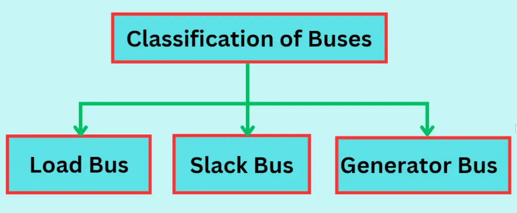
In load flow studies, buses are classified into three categories: generation bus, load bus, and slack bus. Two variables are known, and two are to be determined depending on the quantity specified.
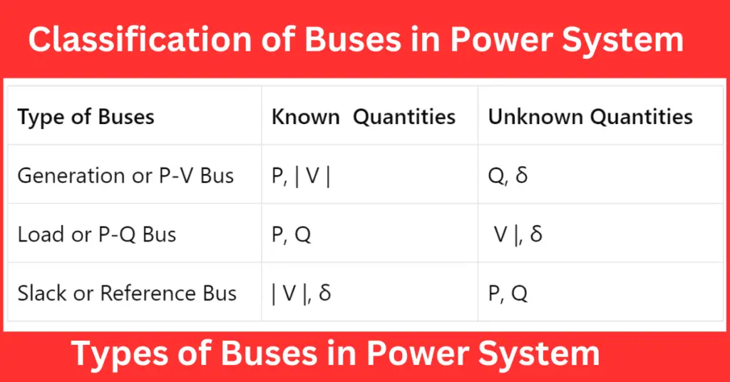
The types of buses in the power system and the associated known and unknown values are shown in the table below.
| Type of Buses | Known Quantities | Unknown Quantities |
| Generation or P-V Bus | P, | V | | Q, δ |
| Load or P-Q Bus | P, Q | V |, δ |
| Slack or Reference Bus | | V |, δ | P, Q |
Generation Bus or Voltage control bus
This type of power system bus is known as the P-V bus. It specifies the voltage magnitude for the generated voltage and the true power or active power P for its rating. To maintain a constant voltage magnitude at a specified value, reactive power is injected. The reactive power generation Q and voltage phase angle δ are to be calculated.
Load Bus
This is also known as the P-Q bus, where active and reactive power is injected into the power grid. The voltage’s magnitude and phase angle need to be calculated. At this bus, the active power (P) and reactive power (Q) are fixed, while the load bus voltage can be allowed to vary within a reasonable range, typically ±5%. The phase angle of the voltage, known as δ, is not critical for the load.
Slack, Swing, or Reference Bus
The slack bus in a power system either absorbs or emits active or reactive power from the power system. Unlike other buses, the slack bus does not carry any load. Instead, at this bus, the magnitude and phase angle of the voltage are specified. Typically, the phase angle of the voltage is set to zero. The active and reactive power of this bus is usually determined by solving equations.
The slack bus can be used as a reference bus for load flow solutions. Typically, one generator bus is designated as the slack bus.
In load flow studies, the slack bus is a theoretical concept used because it’s difficult to predict the I2R losses of the system accurately. This makes it impossible to specify the total injected power at every bus. Typically, the phase angle of the voltage at the slack bus is taken as the reference or zero.