HART protocol is the abbreviation of Highway Addressable Remote Transducer. HART protocol is the global standard to send and receive digital information across analog wires between the smart devices and control/monitoring systems or maybe the hand-held communicators.
HART protocol is a bidirectional communication protocol. It is a protocol that provides access between the intelligent field instruments and the host systems such as DCS, PLC, or hand-held communicators. Here the host could be a software application in the handheld device or laptop for plant process control, safety, asset management, or else some control system that uses any control platform.
HART protocol has become more popular because of its ability to support the conventional 4-20 mA analog protocol while adding an advantage by including major advantages of digital smart instrumentation. The physical communication technology and commands utilized by different applications are also mentioned in the HART protocol.
Architecture of HART Protocol
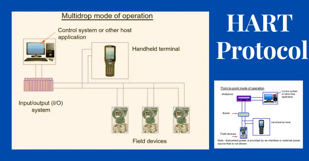
The HART protocol is able to operate in two types of network configurations, point-to-point and multi-drop configurations. The HART protocol uses the master-slave mode or the burst mode.
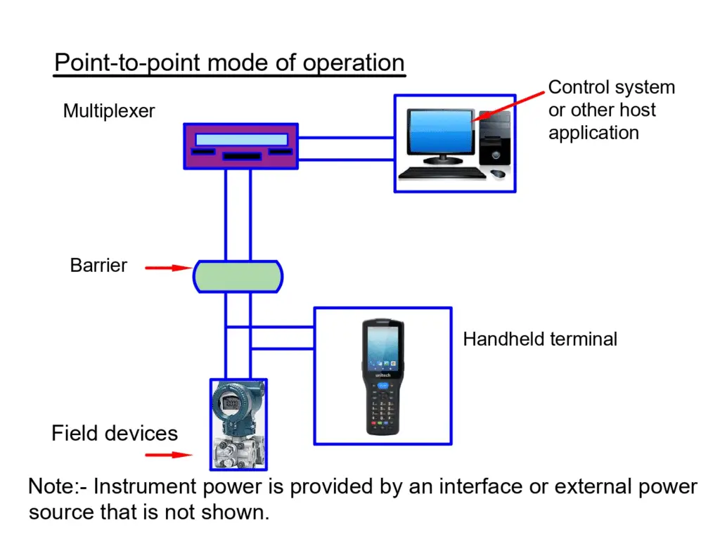
Point to point Configuration of the Network
In point to point type of configuration, to communicate a single process variable, the fixed 4-20 mA signal is used. The extra process variables and design parameters are communicated digitally with the use of the HART communication protocol. Thus, the 4-20 mA signals remain unchanged and can be used in the normal way. It also allows the entry of secondary variables and other data for utilization in maintenance, commissioning, operations, and diagnostic purposes.
Here, there can be two masters: one primary and the other secondary master. The secondary masters, generally hand-held communicators, can be used without interfering with the communications with the primary master, generally a control or monitoring system.
In the burst mode, a single slave device has the ability to continuously broadcast a standard HART reply message. In burst mode higher update rates are possible. Burst mode is generally limited to point-to-point configuration.
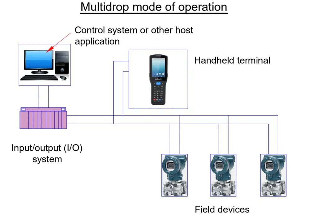
Multi-drop Configuration of Network
In the multi-drop type of configuration, many devices can be connected by using a single pair of wires. Multi-drop configuration can also connect safety barriers and auxiliary power supply for up to 15 field devices. The communication within this configuration is entirely digital. This is because the communication by the analog loop current will be disabled, due to the fact that current from each device will be fixed at a minimum sufficient value for the device to operate. The current is generally fixed at 4 mA. In multi-drop mode, the polling addresses of each field device will be greater than zero.
Modes of Communication of HART Protocol
HART protocol has two modes of communication. They are: master-slave mode and burst mode.
Master Slave Mode
HART protocol generally uses master-slave communication. Each field device acts as a slave and the control/monitoring system acts as the master. The handheld devices or PCs can also act as secondary masters. So in the normal operations, a master will initiate communication with each slave. In each
HART loop, a maximum of two masters can be connected. In such a case, the primary master is generally a DCS, PLC or a personal computer. For example: field instruments like transmitters, valves, and different controllers respond to the commands from the primary or secondary master.
Burst Mode
Some HART devices support the burst communication mode. It enables a faster communication rate, typically the rate is 3-4 data updates per second. The master, in this mode, would instruct the slave device to continuously broadcast the standard HART reply message. An example of a standard HART reply message is the value of a process variable. The master will be receiving messages from the slave at a very high rate. The slave will only stop bursting when the master asks to stop busting.
Command Sets in HART Protocol
The command sets in HART include the following three classes: universal, common practice, device specific.
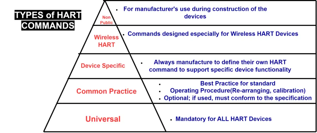
Universal
All the devices that use the HART protocol should recognize as well as support the universal commands. Universal commands provide access to the information which is useful in normal operations. Universal commands are used by the controller to identify a field device and also read process data.
For example, this includes reading a primary variable (PV) and units, reading manufacturer and device type, writing polling address, etc.
Common Practice
Common practice commands will provide the functions that are implemented by many HART communication devices. It is not necessary that all the devices have them.
For example, write damping time constant, calibrate (i.e., set zero, set span), set fixed output current, etc.
Device Specific
Device-specific commands will represent the functions that are unique for each field device. Device-specific commands access setup and calibration information. Device-specific commands also have information about the construction of the device. The information on device-specific commands is made available from the device manufacturers.
For example, read or write low flow cut-off, trim sensor calibration, travel limits, valve characterization, etc.
HART Protocol Specifications
HART protocol Specifications will implement the 1,2,3,4 and 7 layers of the OSI model (Open System Interconnection model).
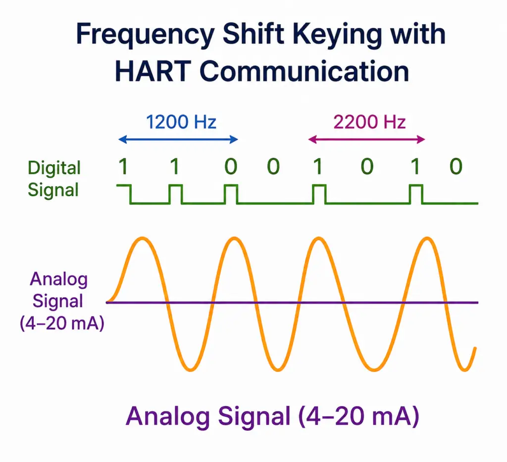
Layer 1: HART Physical Layer
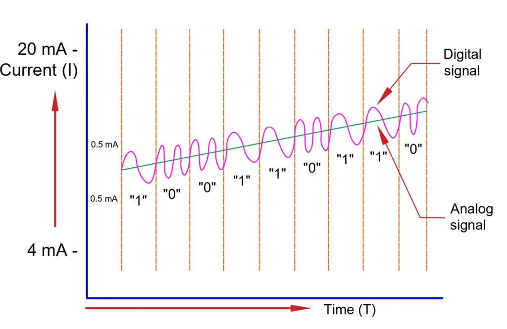
The acronym of “HART” is Highway Addressable Remote Transducer. The HART physical layer is based on the Bell 202 standard. The HART physical layer uses frequency shift keying (FSK) for communication at a rate of 1200 bps. Here the signal frequencies that represent bit values 0 and 1 are 2200 and 1200 Hz respectively. This signal will be then superimposed without using any interface with the analog signal at a low level on the conventional 4-20 mA analog measurement signal.
Layer 2: HART Data Link Layer
The HART Data Link layer will define a master-slave protocol. In the normal case, a field device will reply only when the communication is initiated by the master. There can be two masters: primary master- a control system, and secondary master- a handheld communicator. There are certain timing rules that are defined so as to when each master will initiate a communication transaction. In a multi-drop configuration, up to 15 slave devices can be connected by a single pair cable.
Layer 3: HART Network Layer
The HART Network layer will provide routing, end-to-end security, and transport services. The HART Network layer will manage sessions in end-to-end communication with corresponding devices.
Layer 4: HART Transport Layer
The HART Transport layer will ensure that the communications take place successfully from one place to another. The HART Transport layer also ensures that the communication is propagated successfully.
Layer 7: HART Application Layer
The HART Application layer will define the commands, responses, data types and status reporting that are supported by the protocol. In this layer, the public commands of the protocol are defined and are divided into four major groups:
HART Application Layer Commands
- Universal Commands: Universal commands will provide functions that must be implemented in all field devices.
- Common Practice Commands: Common practice commands will provide functions that are common to many but not to all functions.
- Device Specific Commands: Device-specific commands provide functions that are unique to a particular field device and are generally specified by the device manufacturer.
- Device Family Commands: Device family commands provide a set of standardized functions for instruments with particular measurement types, also allowing full generic access without using device-specific commands.
Difference Between HART Protocol and Modbus Protocol
| Factor | HART Protocol | Modbus Protocol |
| Signal Type | HART is a hybrid protocol combining analog and digital signals. | Modbus is a pure digital data communication protocol. |
| Typical Use | Extensively used in process & instrumentation loops directly on smart field devices. | Normally used for transmitting registers from control systems to a SCADA or main controller. |
| Network Topology | Operates primarily in Point-to-Point and Multi-Drop network typologies. | Operates primarily via Master-Slave (RTU variant) or Client-Server (TCP variant). |
Advantages of HART Protocol
The advantages of HART Protocol include the following:
- HART protocol helps in gaining early warnings against variances in devices, products, or process performance.
- It decreases system downtimes because of equipment failure by recognizing potential technical troubles before they happen.
- This framework helps to speed up the troubleshooting time taken between the identification and resolution of problems.
- It significantly reduces factory inventory costs and field device maintenance overhead.
- The system increases asset productivity and overall loop availability.
- It enhances safety integrity levels (SIL) by utilizing advanced digital diagnostics.
- Using this technology reduces long-term maintenance costs.
- The architecture offers exceptional operational flexibility due to its digital capability, analog backward compatibility, and universal interoperability.
- It helps in improving regulatory compliance across process plants.
Disadvantages of HART Protocol
- Limited Data Transmission Speed: The digital signal data rate utilizing Frequency Shift Keying (FSK) modulation is relatively slow, running at a fixed 1200 bps. Because of this slow response time, it is generally sufficient only for monitoring systems where the process variables do not vary quickly.
- Analog Loop and Node Restrictions: When deployed in a multi-drop network arrangement, the 4-20 mA analog tracking signal is no longer accessible. Furthermore, the number of smart devices that can share a single transmission line is strictly limited.
- Throughput Constraints: The protocol exhibits a slower refresh cycle when compared directly to dedicated, high-speed industrial Fieldbus architectures like Profibus PA or Foundation Fieldbus, creating performance bottlenecks in highly critical or rapid industrial applications.
- Multivariable Digital Overhead: While the digital channel can technically transmit multiple variables simultaneously (such as mass, density, and temperature on a single cable), retrieving this dense secondary data sequentially adds extra time delays compared to pure digital networks.
Applications of HART Protocol
- Multivariable Instrument Integration: It is heavily utilized in complex process loops where a single field instrument measures multiple values—such as mass flow meters tracking volumetric flow, mass flow, density, and temperature simultaneously over one physical cable.
- Smart Device Commissioning and Testing: Field engineers use the protocol alongside handheld configurators or asset management software to loop-test, configure, and calibrate smart transmitters and control valves remotely.
- Industrial Process Control: It acts as the primary diagnostic link in chemical, oil and gas, and water treatment industries to seamlessly network intelligent field hardware with distributed control systems (DCS) and PLCs.
- Predictive Maintenance Arrays: Plants deploy it to pull device status and diagnostic alerts continuously, allowing asset management systems to flag a fading sensor before an active process loop fails.
Conclusion
The HART protocol remains a dominant global standard in industrial automation by seamlessly bridging the gap between legacy 4-20 mA analog infrastructure and modern digital diagnostics. As a robust bidirectional communication framework, it ensures that field engineers and plant operators can extract critical secondary process variables, configuration data, and predictive alerts directly from smart field devices.
Whether interfacing with a local handheld communicator, a plant-wide Distributed Control System (DCS), or a Programmable Logic Controller (PLC) array, implementing the HART protocol maximizes loop reliability, simplifies device maintenance, and ensures long-term operational efficiency across the process industries.
Frequently Asked Questions (FAQs)
A standard HART protocol digital signal can be transmitted up to 3,000 meters (approx. 10,000 feet) over a single twisted pair of shielded 18 AWG gauge wire. The exact maximum distance depends on the loop impedance and the cable capacitance.
No, a standard digital multimeter cannot read the digital FSK communication because it only measures the average DC value of the 4-20 mA current loop. To view, parse, or configure the digital data layer, you must use a dedicated handheld HART communicator, a HART-to-USB modem with asset management software, or a HART-compatible analog input card.
A Device Description (DD) is a specialized electronic data file written in Device Description Language (DDL). It acts as a driver for the smart field device, telling the host control system or handheld communicator exactly how to read, interpret, and display the instrument’s unique internal parameters, menus, and calibration options.
In a multi-drop configuration, the 4-20 mA analog signal loop current is disabled and locked at a fixed minimum value of 4 mA per device. Because the current does not change with the process variable, all process measurement data must be transmitted completely through digital polling addresses (ranging from 1 to 15).
The primary difference is that 4-20mA is an analog physical signaling method, while HART is a digital communication protocol that rides on top of that analog signal.
4-20mA loop: A traditional analog current loop that can only transmit one process variable in one direction with zero diagnostic data.
HART Protocol: A hybrid protocol that superimposes a bidirectional digital signal onto the same 4-20mA wires using Frequency Shift Keying (FSK). It allows smart devices to send multiple process variables, device configurations, and advanced diagnostics without affecting the primary 4-20mA analog control signal.
Read Next: