LVDT and RVDT are electromechanical transducers used to measure displacement and convert it into an electrical signal. LVDT (Linear Variable Differential Transformer) measures linear displacement, while RVDT (Rotary Variable Differential Transformer) measures angular displacement. Both devices operate on the principle of electromagnetic induction and are widely used in automation, process control, aerospace, and industrial measurement systems.
In this article, we will discuss the working principle, construction, applications, and key differences between LVDT and RVDT.
What is LVDT?
LVDT (Linear Variable Differential Transformer) is an electromechanical transducer used to measure linear displacement and convert it into a proportional electrical signal. It operates on the principle of mutual induction and provides accurate, frictionless, and reliable position measurement.
Construction of LVDT
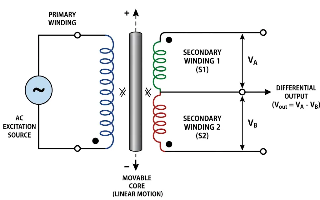
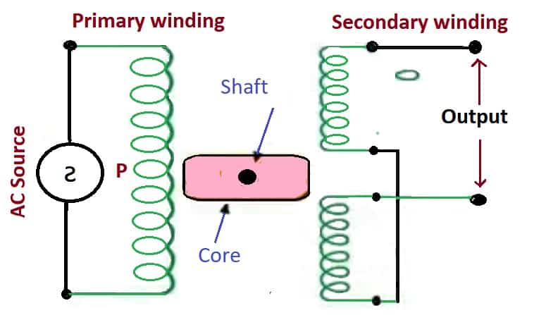
An LVDT consists of a primary winding placed between two identical secondary windings wound on a hollow cylindrical former. The secondary windings are connected in series opposition. A movable ferromagnetic core is positioned inside the coil assembly and is free to move linearly along its axis.
How LVDT works?
An LVDT works on the principle of mutual induction. When an AC excitation voltage is applied to the primary winding, it produces a magnetic field that induces voltages in the two secondary windings through the movable ferromagnetic core.
- When the core between the two secondaries is in the center position, the voltages induced across both windings are equal. The final voltage is zero because both secondary windings are connected in series & in phase opposition.
- If the core moves in the direction of secondary-1, the voltage increases in secondary-1, and the voltage decreases in secondary-2. Similarly, if the core moves in the direction of secondary 2, the voltage increases in secondary-2, and the voltage decreases in secondary-1.
- Thus the final net voltage VA – VB is of the same polarity (in-phase) as the reference. If the core moves in the opposite direction, VA – VB will be of opposite polarity (180º out of phase).
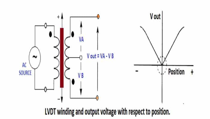
Therefore, as the ferrite core moves along its axes within the LVDT, the output voltage starts with one polarity, decreases completely to zero. later increases with opposite polarity, all in a continuous and smooth way.
Thus, the output voltage of an LVDT is directly proportional to the displacement of the movable core within its linear operating range.
LVDTs give a linear output voltage signal around zero (within the ± 0.25% over a specified linear range of travel).
For a typical LVDT selection, the linear range nominal can be from ± 0.05 inches to ± 10 inches, with the body corresponding to lengths from 1 inch up to 30 inches.
LVDTs are rugged and accurate, and they produce low-voltage outputs. (the Sensors – Conditioners – Processors sensitivity is between 6.3 and 0.08 mV per volt of excitation per millimeter of displacement) and therefore they need a lot of care, attention when doing amplification.
LVDT Signal Conditioning
The output of an LVDT consists of two AC signals that are 180° out of phase. A signal conditioner converts these AC signals into a proportional DC voltage that represents the position of the movable core.
To perform this AC-to-DC conversion, a demodulation technique is required. The most commonly used method for LVDT signal conditioning is synchronous demodulation.
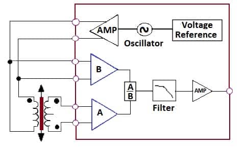
In synchronous demodulation, the excitation of the primary serves as the reference for the demodulator. The demodulator half-wave rectifies the a.c. the signal then is low-pass filtered to produce a d.c output. Whose magnitude shows the movement (position) away from the central position and whose sign indicates the direction.
The LVDT signal conversion method uses a large number of discrete components and built-in, as shown below, where you have four sections: Oscillator / Driver, Drive Amplifier, input, demodulator, and low-pass filter. With the introduction of signal conditioning devices, Analog Devices supports the signal conditioning applications of LVDTs.
What is RVDT?
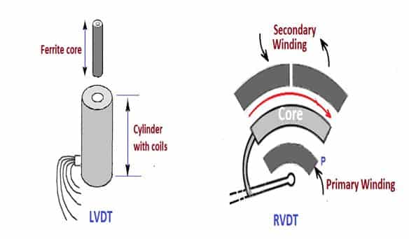
RVDT (Rotary Variable Differential Transformer) is an electromechanical transducer used to measure angular displacement and convert it into a proportional electrical signal. It operates on the same differential transformer principle as an LVDT but is designed for rotational movement.
RVDT Construction
The construction of an RVDT is similar to that of an LVDT, except that the ferromagnetic core rotates through a limited angle instead of moving linearly. An RVDT consists of a primary winding and two secondary windings connected in series opposition. A cam-shaped rotor mounted on a shaft rotates between the windings, changing the magnetic coupling and producing an output voltage proportional to the angular displacement.
How RVDT Works?
When an AC voltage is applied to the primary winding, magnetic flux is generated and coupled to the secondary windings through the rotating ferromagnetic rotor. At the null position, equal voltages are induced in both secondary windings, resulting in zero output voltage. As the rotor rotates clockwise or counterclockwise, the induced voltages become unequal, producing a differential output voltage proportional to the angular displacement.
While LVDTs measure linear displacement, RVDTs measure angular displacement. The maximum angular position measurement range is approximately ± 60º.
When RVDTs work in the range of ± 40º, the typical device has a linearity error of 0.2% of full scale. If the angular displacement is maintained within ±5°, the linearity error reduces to less than 0.1% of full scale. The shaft is supported by ball bearings that minimize friction and mechanical hysteresis.
Difference Between LVDT and RVDT
Both LVDT and RVDT operate on the principle of mutual induction and differential transformer action. However, LVDT measures linear displacement, whereas RVDT measures angular displacement. In an LVDT, the ferromagnetic core moves linearly inside the transformer windings. In contrast, the rotor of an RVDT rotates through a limited angular range.
Due to these differences, LVDTs are widely used in valve position measurement, hydraulic actuators, and industrial automation, while RVDTs are commonly used in servo mechanisms, radar systems, and aerospace control systems.
Comparision Table: LVDT Vs RVDT
| Parameter | LVDT | RVDT |
| Full Form | Linear Variable Differential Transformer | Rotary Variable Differential Transformer |
| Measures | Linear displacement | Angular displacement |
| Core Movement | Linear | Rotational |
| Core Shape | Cylindrical/Ferromagnetic Core | Cam-shaped Rotor |
| Measurement Range | Typically ±100 μm to ±25 cm | Typically ±40° to ±60° |
| Sensitivity | Approximately 2.4 mV/V per unit displacement | Approximately 2–3 mV/V per degree of rotation |
| Applied Input Voltage | 1 V to 24 V rms | Typically 3 V rms |
| Frequency Range | 50 Hz to 20 kHz | 400 Hz to 20 kHz |
| Output | Proportional to linear displacement | Proportional to angular displacement |
| Applications | Position sensing, hydraulic actuators, load cells, pressure measurement, and product inspection | Servo systems, radar systems, antenna positioning, aerospace, and control systems |
Applications of LVDT and RVDT
- Used in measurement and control applications for sensing displacement from a few micrometers to several feet.
- Widely used in metrology systems for precise position measurement.
- Used for valve position monitoring and hydraulic actuator control.
- LVDTs are commonly used in load cells and pressure sensors.
- Applied in brake-by-wire and cable-operated control systems.
- Used in engine bleed-air systems and engine fuel control systems.
- Extensively used in aircraft and avionics applications.
- Employed in process control and industrial automation systems.
- Used in environmental and ecological control systems.
Conclusion
LVDT and RVDT are widely used electromechanical transducers for displacement measurement in industrial, aerospace, and control applications. Both devices operate on the principle of electromagnetic induction and provide accurate, reliable, and frictionless position sensing. The main difference between them is that an LVDT measures linear displacement, whereas an RVDT measures angular displacement. Due to their high accuracy, long service life, and excellent repeatability, LVDTs and RVDTs remain popular choices for position measurement and control systems.
Frequently Asked Questions (FAQs)
LVDT stands for Linear Variable Differential Transformer. It is an electromechanical transducer used to measure linear displacement.
RVDT stands for Rotary Variable Differential Transformer. It is used to measure angular displacement and convert it into an electrical signal.
The main difference is that LVDT measures linear displacement, whereas RVDT measures angular displacement. Both devices operate on the same differential transformer principle.
Both LVDT and RVDT work on the principle of electromagnetic induction. A change in the position of the core or rotor alters the magnetic coupling between the primary and secondary windings, producing a differential output voltage.
LVDTs and RVDTs are used in metrology systems, hydraulic actuators, valve position monitoring, aircraft and avionics systems, industrial automation, process control systems, and displacement measurement applications.
Read Next:
Good article,