The polarity test of the transformer is performed to determine the direction of induced voltages in the primary winding and the secondary winding. The polarity test is essential for the proper connection of parallel-operated transformers.
Some key aspects are given below that require knowledge of the polarity of the transformer:
- Parallel connection of two or more transformers.
- To construct a three-phase transformer bank.
- To connect current and potential transformers for measurement of current and voltage, respectively.
- To connect protective devices like relays with the transformer, etc.
Let us now discuss the polarity test of the transformer in detail.
Polarity Test of Transformer
In an electrical transformer, the polarity test is performed to determine the terminals of the same instantaneous polarity of the induced EMF.
In a two-winding transformer, the dot convention or notation is used to determine the polarity of voltage induced by the mutual inductance between the two windings.
According to the dot convention:
- If an electric current enters the dotted terminal of the primary winding, the induced voltage in the secondary winding will have positive polarity at the dotted terminal.
- If an electric current leaves the dotted terminal of the primary winding, the polarity of the induced voltage in the secondary winding will be negative at the dotted terminal.
We can perform the following two types of polarity tests on a transformer:
- Additive Polarity
- Subtractive Polarity
Let us now discuss each of these tests in detail.
(1). Additive Polarity:
The circuit diagram of the additive polarity is shown below.
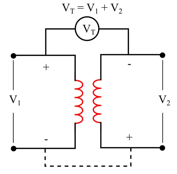
In the case of additive polarity, the voltage between the primary winding and the secondary winding will be the sum of both the primary winding voltage and secondary winding voltage, i.e.,
Here, VT is the voltage between the primary and secondary windings. The voltage V1 and V2 are primary winding voltage and secondary winding voltage, respectively.
The additive polarity is used for small distribution transformers.
(2). Subtractive Polarity:
The circuit diagram for the subtractive polarity test is shown in the following figure.
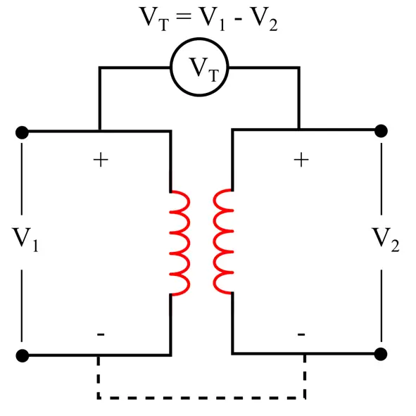
In the case of subtractive polarity, the voltage between the primary winding and the secondary winding is the difference between the primary voltage and secondary voltage, i.e.,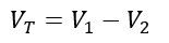
In the subtractive polarity test, if the voltage VT > 0, the given transformer is a step-down transformer, and if VT < 0, the transformer is a step-up transformer.
The subtractive polarity test is used for large power transformers.
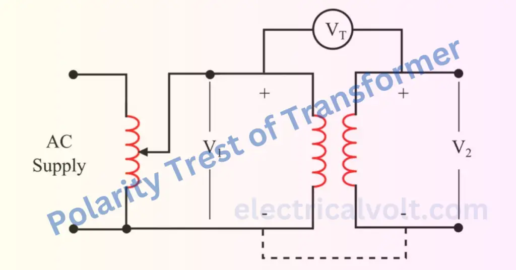
How to Perform Polarity Test of Transformer?
The step-by-step procedure to perform the polarity test of a transformer is given below:
Step (1) – Arrange the circuit as shown in the following figure.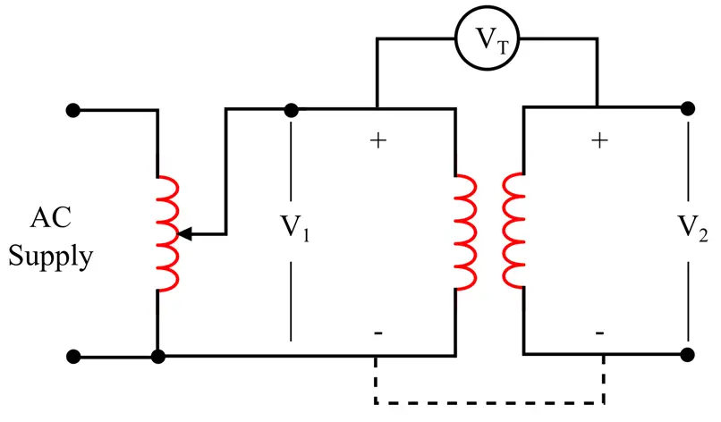
Step (2) – If possible, note down the ratings and turn ratio of the transformer.
Step (3) – Connect a voltmeter between the primary and secondary windings of the transformer.
Step (4) – Apply a voltage V1 to the primary winding with the help of an autotransformer.
Step (5) – By observing the reading of the voltmeter, we can determine whether the polarity is additive or subtractive as follows:
- If the polarity is additive, the voltmeter will show the sum of voltages V1 and V2.
- If the polarity is subtractive, the voltmeter will show the difference in the voltages V1 and V2.
Important Points
The following are some important points to be noted while performing the polarity test of a transformer:
- The maximum measurable voltage range of the voltmeter must be greater than the sum of V1 and V2.
- If we need the additive polarity but have the subtractive polarity. It can be obtained simply by changing the connection of the primary or secondary winding while keeping the secondary or primary winding connections as they are.
- If we need the subtractive polarity but have the additive polarity. Then, we reverse the connection of the primary or secondary winding while keeping the secondary or primary winding as it is.