We can know the different components of the transformer and connections by a power transformer diagram. The power transformer diagram shows the interconnections of the different parts of the transformer and the electrical circuit of it.
The transformer steps up and steps down the voltage according to the desired applications, thus a transformer changes voltage from one level to another. They have primary and secondary winding wrapped around a magnetic core. The primary and secondary winding turns decide to step up or step down the voltage. The primary winding receives AC power, and the secondary winding feeds power to the load.
A power transformer has parts, such as a magnetic core, a primary winding, a secondary winding, a tap changer, a set of bushing, a Buchholz relay, a conservator tank, a pressure relief valve, and a cooling system. A power transformer diagram shows how all these components are connected to each other and how these components are connected with a power source and load.
It is paramount to understand the power transformer diagram for a better understanding of how the transformer parts are connected and how they contribute to transformer operation. It is important that everyone, who works on the transformer, including engineers, electricians, and technicians, must understand the transformer diagram so that they can identify faults, troubleshoot problems, and make necessary repairs.
Before understanding more about the transformer diagram, let us understand the transformer working principle and parts of the transformer.
Transformer Working Principle
The transformer functions on the principle of Faraday’s law of electromagnetic induction. The AC voltage is fed to the primary winding. It induces a time-varying magnetic flux in the core and links to the secondary turns of the transformer. The linking flux to secondary winding induces EMF.
Thus, a transformer changes the voltage level without changing the power and frequency.
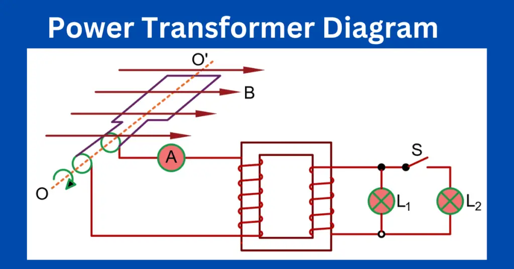
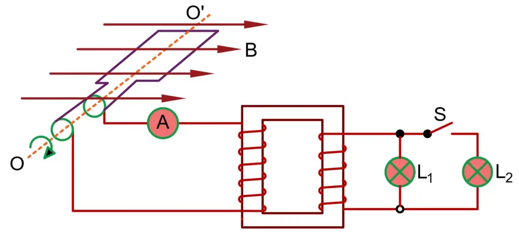
Power Transformer Diagram
A power transformer’s diagram comprises trading voltages for currents without affecting the electrical power. This means that the transformer converts low-voltage to high-voltage with a small current change to a large current, or vice-versa.
Parts of a Transformer
Before understanding the transformer diagram, it is a must to know the transformer’s part. The followings are the main parts of a transformer.
Primary Winding
A transformer consists of two winding- primary and secondary winding. The primary winding is made of copper or aluminum conductor. It draws power from the AC source and sets up magnetic flux in the magnetic core. The magnetic flux depends on the voltage and frequency of the supply source.
Secondary Winding
The secondary winding is made of copper or aluminum. It receives the varying magnetic flux set up by the primary winding. The flux links to the secondary winding and induces EMF across the winding. The induced voltage in the secondary depends on the turn ratio of the transformer. The secondary winding feeds power to the electrical load.
Transformer Core
A transformer core is made of CRGO steel and its main function is to carry the magnetic flux. Thus, it provides the path to magnetic flux. The eddy current loss and hysteresis loss occur in the core and adequate cooling to the transformer is done by providing the Colling ducts within the core
How to Read a Power Transformer Diagram?
A transformer diagram represents the electrical connections and circuity of a power transformer. It helps in understanding the operation, functionality, and design of a transformer. The followings are some tips for reading a diagram.
Identify the Transformer Type
There are different types of transformers. These include a step-up transformer, step-down transformer, autotransformers, isolation transformer, and others. Each type of transformer has different applications and unique diagrams. Therefore, when you read the transformer diagram, you can find out which type of transformer it is.
Understand the symbols
The transformer diagram has symbols that represent the electrical connections and components of the transformer. The symbols of the transformer comprise the primary winding, secondary winding, transformer core, tap changer, and ground. By understanding these symbols, we can interpret the diagram easily.
Number of Phases
There are two types of transformer- single phase and three phase. For delivering a large power three phase transformer is used. We can identify the number of phases and voltage and current level by reading the power transformer diagram.
Flow of Electricity
We can find the flow of electricity through the transformer using a transformer diagram. The diagram indicates the primary and secondary voltage levels, the number of the primary and secondary winding, the tap changer with high voltage winding, and connections between the coil. The flow of electricity through the transformer helps in understanding the transformer’s functionality.
Refer Manufacturer’s Documentation
If you have difficulty in understanding the transformer diagram, the manufacturer’s document can be referred to for a better understanding or you can consult a qualified electrical engineer.
By following the above tips, you can have a better understanding of power transformer diagrams and their purpose. Every engineer, electrician, or technician working on a transformer must insightfully understand the diagram.
Tips for Reading a Power Transformer Diagram
1. Identify the Transformer Type
Identify whether the diagram represents a single-phase or three-phase transformer. Single-phase transformers have two primary terminals marked as (H1, H2) and two secondary terminals marked as (X1, X2). Whereas, three-phase transformers have three primary terminals (H1, H2, H3) and three secondary terminals (X1, X2, X3).
2. Primary and Secondary Windings
The winding connected to the supply side is the primary winding and the winding connected to the load is the secondary winding. Locate both winding on the diagram Locate the primary and secondary windings on the diagram.
3. Identify the Phases
Each phase indicates a set of primary and secondary winding. The primary windings are labeled with the phase designations, such as H1, H2, H3, and X1, X2, and X3 for the secondary side.
4. Identify the Transformer Rating
The rating of the transformer is expressed in kVA and it indicates the power handling capacity. This information is mentioned within the diagram.
5. Determine the Winding Polarities
The winding polarities show the direction of the winding turns. The polarities play an important role in determining the phase relationship between the voltage and current of the transformer. The polarity markings is done using a dot notation. A dot symbol on one side of the winding represents the starting point of the winding.
6. Connection Types
The transformer diagram also indicates the connection types of the primary and secondary winding. The connection types of winding are of Delta (Δ), Wye (Y), or Zigzag (Z) type. These connection types show the voltage and phase relationship between windings.
7. Identify the Tap:
Some transformers have tap changers – on-load or off-load, to adjust the voltage. These taps are indicated by additional terminals on the diagram, such as H4, H5, etc., for the primary side, and X4, X5, etc., for the secondary side.
8. Other Components
The diagram also has symbols or labels for other components associated with the transformer, such as fuses, circuit breakers, cooling systems, and protective devices.
Regenerate response
Why is it important to know how to read a power transformer diagram?
A power transformer diagram is a tool for understanding the working of a transformer and its installation and maintenance of it. It helps in troubleshooting problems and therefore it is important to know how to read it.
What transformer components are shown in a power transformer diagram?
The following components are shown in a diagram.
- Primary winding
- Secondary winding
- Transformer core
- Tap changer
- Protective devices- fuses and circuit breakers
State the difference between a single-phase and three-phase transformer diagram.
A single-phase transformer has one primary and one secondary winding. On the other hand, the three-phase transformer has three primary winding and three secondary winding. The connections in a three-phase transformer is different than single phase transformer.
How do you use a transformer diagram to troubleshoot a power transformer?
Check the voltage and current at various points referring to the transformer diagram. Further, test the transformer using the test equipment to identify the problem. Thus, a diagram helps in troubleshooting the problem.
Can you modify a power transformer diagram?
If you do any changes in the configurations or connections, you can modify the diagram. However, modifications in the transformer connections are a specialized job and it must be done by a qualified electrical engineer.