An electrodynamometer wattmeter is defined as an electrical measuring instrument that is used to estimate both the AC and DC powers of the electrical and electronic circuits. The device functions based on the interaction between the magnetic flux of the moving and fixed coils in the device. It operates on the principle of dynamometer, which states that current-carrying conductors experience a mechanical force when placed in an existing magnetic field.
In this article, we will discuss the electrodynamometer wattmeter, its construction, advantages, and disadvantages. Let’s start with a basic introduction to the electrodynamometer wattmeter.
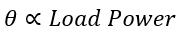
Construction of Electrodynamometer Wattmeter
The diagram of electrodynometer wattmeter is shown in the image below.
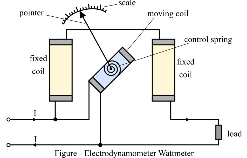
The electrodynamometer wattmeter is comprised of the following components.
1. Moving Coil
It is also referred to as the pressure coil of the measuring device. The moving coil, also called the potential coil, is connected in parallel to the input supply voltage. The current passing through the moving coil directly relates to the supply voltage. A pointer is connected to the moving coil, and it deflects with the help of the spring attached to it. The current flow through the moving coil is limited by the multiplier resistor connected in series with the moving coil.
2. Fixed coil
It is also referred to as the current coil, as the current from the load flows across it. To ease the construction of the measuring instrument, the fixed coil is subdivided into two identical parts placed parallel to each other. Both the fixed coils generate a constant magnetic field that is necessary for the efficient functioning of the device. The fixed coils carry a current of around 20 amperes in magnitude for the purpose of conserving power.
3. Control
The control system of the electrodynamometer generates the controlling torque. There are two kinds of control systems: spring control and gravity control systems. The spring control system is present within the electrodynamometer wattmeter. This system is utilized for the purpose of deflecting the pointer attached to the moving coil.
4. Damping
Damping is defined as the effect that minimizes the deflection of the pointer. The air friction generates the damping torque in the case of the electrodynamometer wattmeter. Besides the air friction damping, no other damping effect is prevalent in this wattmeter as they might damage the magnetic field generated by the coils.
5. Pointers and scales
The linear scale is utilized in the electrodynamometer wattmeter as the moving coil moves in a linear manner. The knife edge pointer is embedded in the wattmeter to reduce the issue of oversights due to parallax errors.
Working of Electrodynamometer Wattmeter
The moving coil carries the current in proportion to the voltage at the load, and the fixed coil carries the load current flowing through it. A mechanical force is exerted between the two coils due to the current flowing across them. This mechanical force results in the movement of the potential coil as well as the deflection of the pointer connected to it.
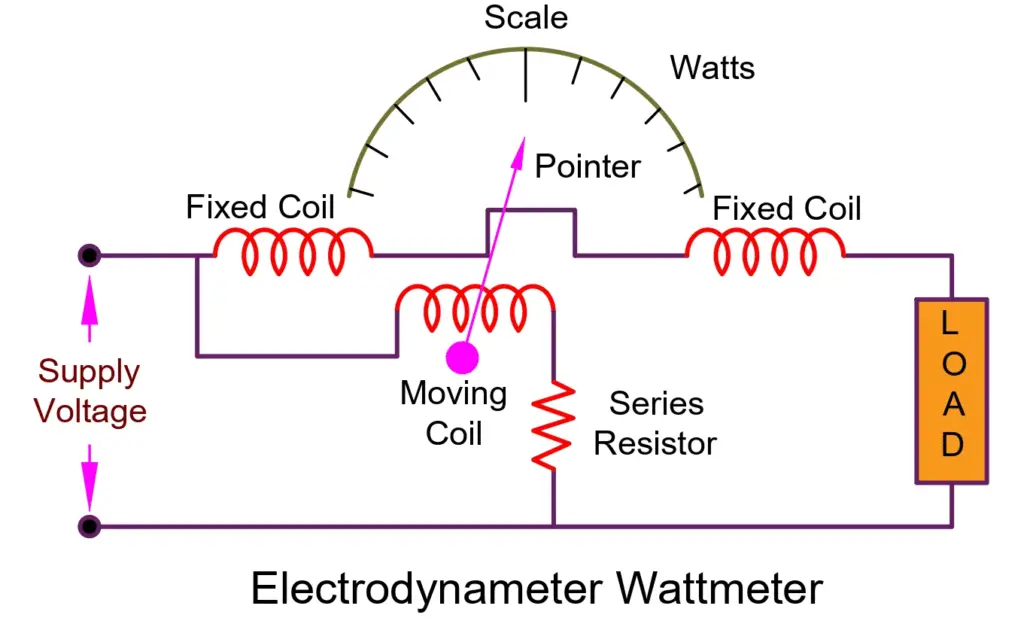
When the deflecting torque and controlling torque are equal, the pointer shows null deflection. As the magnitude of deflecting torque remains constant even when the current polarity in the circuit is reversed, the electrodynamometer wattmeter instrument can be used for measuring both DC and AC powers in the circuit.
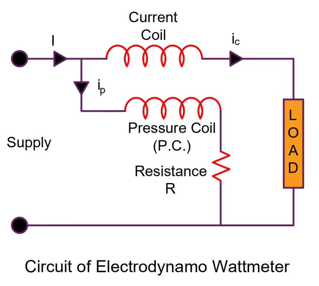
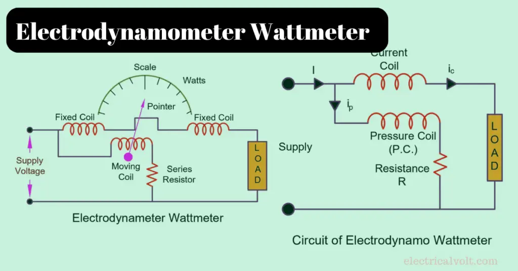
Theory of Electrodynamometer Wattmeter
The circuit diagram of the electrodynamometer wattmeter is shown in the figure below.
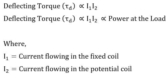
Mathematically, the load powers of the DC and AC circuits are directly proportional to the deflecting torque of the electrodynamometer wattmeter instrument.
Behavior in DC Circuit
Let the power of the load be VI1, when the electrodynamometer wattmeter instrument is connected to a DC circuit. The mathematical relationship between the currents in the coils and the deflecting torque is as follows.
Behavior in AC Circuit
Let the power of the load be VI1, when the electrodynamometer wattmeter instrument is connected to an AC circuit. The mathematical relationship between the current in the coils, voltage, and Instantaneous deflecting torque is as follows.
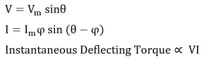
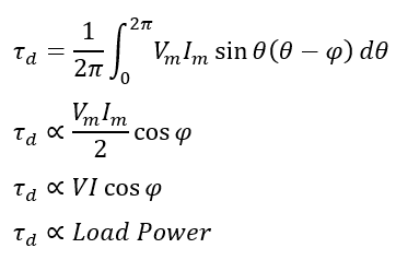
The deflecting pointer of the wattmeter is unable to read the instantaneous power of the systems as it is changing at a very fast rate. Therefore, due to the existing inertia of the moving pointer, the wattmeter measures the average value of the load power. The relationship between the average and instantaneous power is as follows.
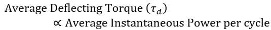
The relation between deflecting torque and load power is as follows.
The controlling torque in the wattmeter is provided by a spring. This means that the spring is responsible for controlling the torque in the wattmeter.

When the system’s circuitry is in equilibrium, the controlling torque and deflecting torque are equal.
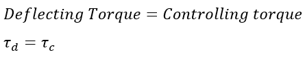
Therefore,
Advantages of Electrodynamometer Wattmeter
- The wattmeter instrument has a uniform scale.
- High precision of the electrodynamometer is achieved by appropriate calibration.
- They are utilized to determine the AC and DC power.
Disadvantages of Electrodynamometer Wattmeter
- Parallax or measurement error: It may be caused by the device having low power factor values due to the moving coil’s inductivity.
- Stray Magnetic Field: The wattmeter instrument may give inaccurate measurements due to the undesired or stray magnetic field from the surrounding environment. To solve this issue, the wattmeter can be placed in a well-protected iron case.
- Pressure Coil Inductance – The inductance of the pressure coil in the Electrodynamometer causes the current to lag behind the voltage, resulting in a lagging power factor and high meter readings.
- Eddy Current Error – The eddy current induced in the coil generates its own magnetic field, which affects the main current flowing through the coil and causes reading errors.
- Pressure Coil Capacitance – The pressure coil’s capacitance increases the instrument’s power factor, causing reading errors due to its inductance.
- Error due to Mutual Inductance Effect – The interaction between the pressure and current coil currents causes mutual inductance, creating a measurement error.
- Temperature Error – The change in temperature affects both the resistance of the pressure coil and the torque provided by the spring, leading to reading errors.
Read Next: