Nodes, branches, and loops are the key concepts for analyzing an electric circuit. An electric circuit can be the combination of two or more network that provides a closed path to electric current. Thus, when we add more networks to form an electric circuit, there are more paths through which electric current flow. Now, we will discuss the nodes, loops, and branches formed in an electric circuit to understand how all these are useful for the analysis of the circuit.
Nodes in a Circuit
Node is fundamental to circuit analysis and plays a significant role in understanding the behavior of electrical circuits.
A node is a connection that is generated between two or more branches. The connection of the elements can form that connection point and can also be formed by a short circuit, that is, a connecting wire. It is a point where two or more circuit elements, such as resistors, capacitors, or other components, connect and share a common connection.
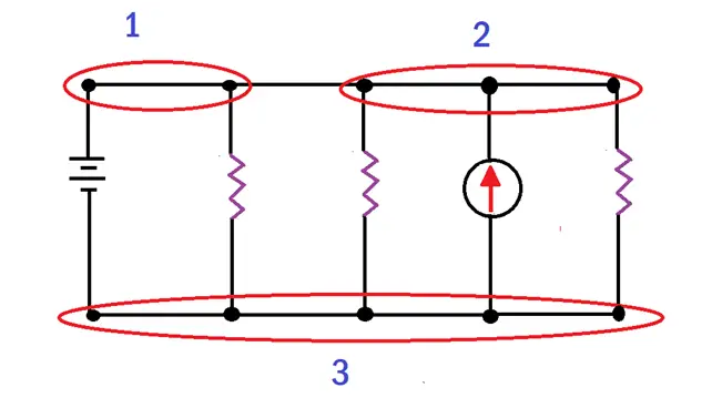
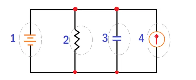
In the above figure, 1, 2, and 3 in red marked circles represent nodes. That means when there are no connected electrical elements, a short circuit (a connecting wire) connects two nodes to constitute a single node, represented as above.
Nodes are very essential for analyzing circuits using various techniques, such as Kirchhoff’s current and voltage laws. Kirchhoff’s current law states that the algebraic sum of currents entering a node is equal to the same total current leaving the node. Kirchhoff’s voltage law states that the sum of voltages entering a circuit and leaving any closed loop in a circuit is zero.
Nodes are often represented by using thick dots in circuit diagrams. Each dot represents a specific point where elements like resistors, capacitors, or others are connected. Using nodes, we can determine voltages and currents and solve circuit equations, which help in predicting the behavior of complete electrical circuits.
The circuit components that lie on the same node have the same voltage irrespective of the extension of connecting line between the components.
The nodes in a circuit diagram are shown in the below image.
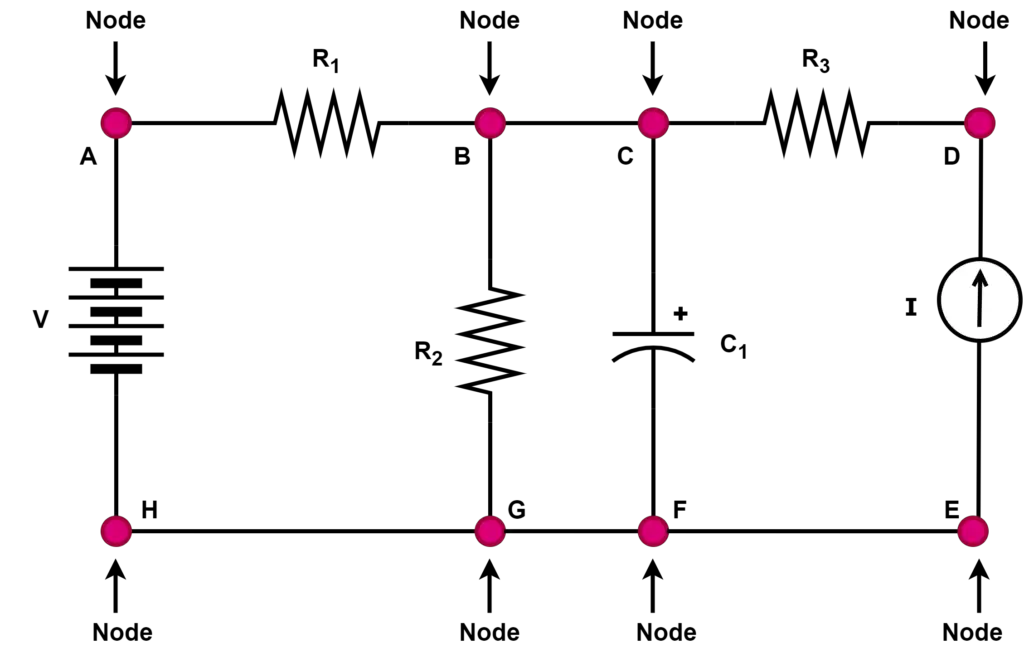
Here, nodes E, F, G, and H are on the same potential. Therefore we can assign these nodes as a single node. Similarly, nodes B and C are on the same potential. we can assign these nodes as a single node. The above circuit can be redrawn as,
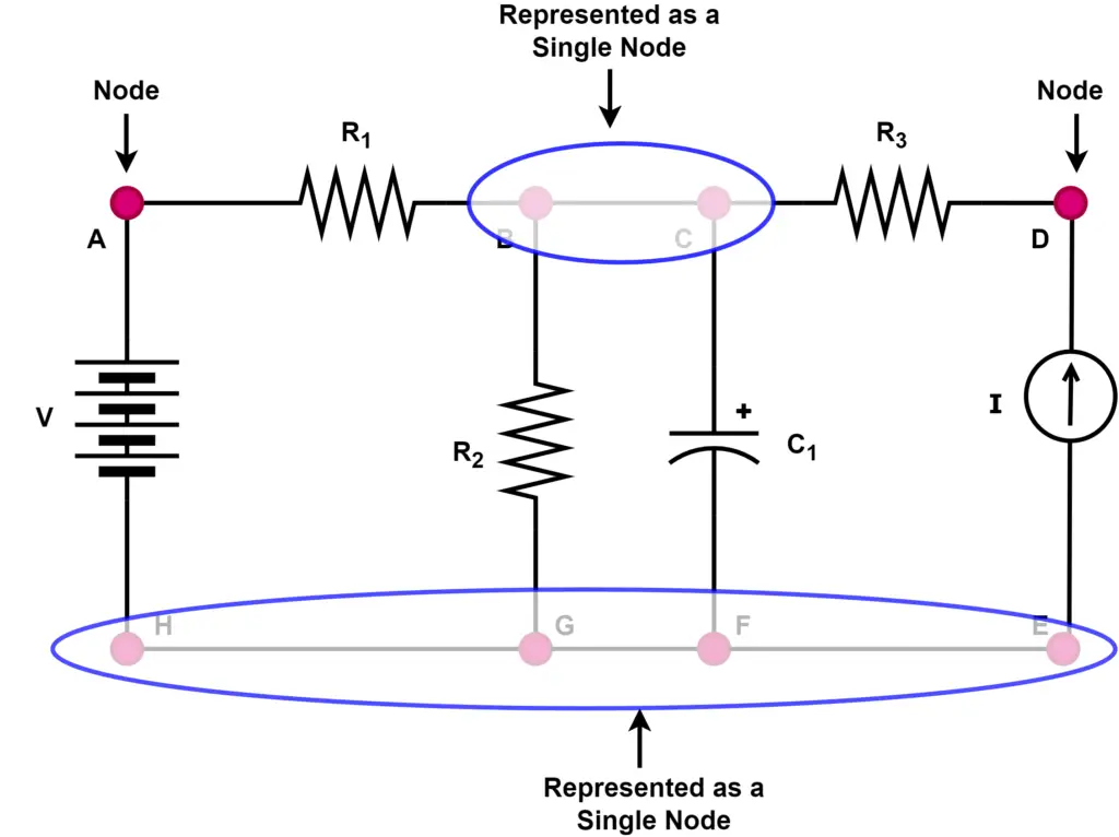
Rule- The nodes at the same potential can be represented as a single node.
Loops in a Circuit
In an electrical circuit, a “loop” refers to a closed path through which electrical current can flow. In electrical circuits, the closed path formed by two or more branches is known as a loop. The term “closed circuit” or “closed loop” is used to describe a loop in an electrical circuit. A loop is formed when a continuous connection of conductive elements such as wires, components, and devices allows electric current to circulate across it.
As an example, let us consider a simple circuit with a battery, a resistor, and a switch. When a switch is closed, it completes the loop, allowing current to flow from the battery through the resistor and back to the battery. In this case, the loop is formed by a wire connecting the battery terminal to one end of the resistor and another connecting the other end back to the battery terminal. The flow of electric charge is through this close path.
Like nodes and branches, the Loops are essential in electrical circuits as they allow the flow of current. As we know, the current flow is essential for operating various electrical and electronic devices and systems. Loops are also closely related to principles like Kirchhoff’s laws, which describe the current and voltage behavior in electrical circuits.
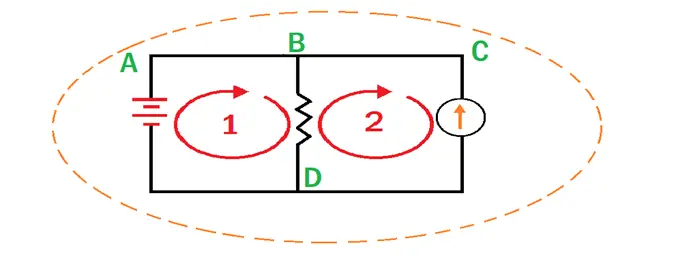
As shown in the above figure, a “Loop” is a closed path that is formed with the connection of the elements of an electrical circuit. This trajectory (path) starts at an initial node in a circuit, passes through different nodes, and returns to the initial point without going through any node more than once.
In the following example, as can be seen, we have three loops:
Trajectory (path) “A-B-D.”
Trajectory (path) “B-C-D.”
Trajectory (path) “A-B-C-D.”
There can be loops within a loop. The loop A-B-D and B-C-D are within loop A-B-C-D.
Branches in Electrical Circuit
In an electrical circuit, a “branch” refers to a separate path or route through which electrical current can flow. A circuit can have multiple branches, each containing its components such as resistors, capacitors, inductors, and other devices. These branches are typically connected to the main circuit or other branches at various points. Like nodes and loops, concepts of branches in a circuit help in solving the electrical network.
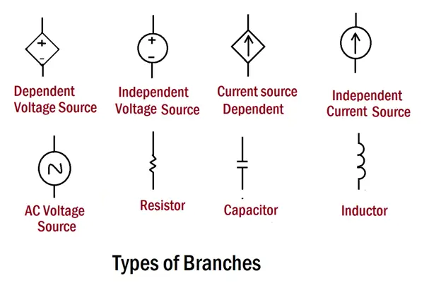
The following electrical components and devices form four branches in an electrical circuit.
1. Voltage source
2. Resistance
3. Capacitor
4. Power source
The concept of branches is important in understanding how currents flow within a circuit. In a parallel circuit, for example, the current has multiple paths (branches) to choose from, and the total current entering a junction is divided among the different branches based on their resistance or impedance. One branch forms in a series circuit when the same current flows through all components. The branch connects two different nodes in a circuit.
Understanding the concepts of branches is essential for circuit analysis and design. It allows circuit designers to predict and control electrical current and voltage behavior within a complex circuit configuration.
Example of Nodes, Loops, and Branches in a Circuit
The nodes, branches, and loops in a circuit are shown in the following figure.
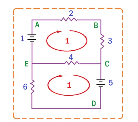
Branches: Contain 6 branches, which are composed of 2 voltage sources and 4 resistors.
Nodes: The circuit contains 5 nodes, marked in green (A, B, C, D, E).
Loops: The circuit contains 3 loops, which are made up of the “A-B-C-E” path (loop 1), the “E-C-D” path (Loop 2), and finally the external dotted line, the “A-B-C-D-E” path.