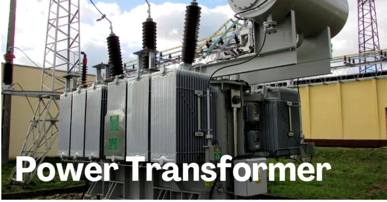
A power transformer is a stationary electrical device designed to transfer energy between two circuits while keeping the frequency unchanged. It operates on the principle of electromagnetic induction, allowing it to either increase (step up) or decrease (step down) the voltage of an AC supply. Power transformers play a vital role in the efficient transmission, distribution, and utilization of electrical energy across industrial, commercial, and utility sectors.
What is a Power Transformer?
A power transformer is a vital electrical device used to transfer electrical energy between two or more circuits through electromagnetic induction. It steps up (increases) or steps down (reduces) voltage levels in high-voltage transmission networks to ensure efficient and reliable power flow.
Power transformers are typically installed in generating stations, transmission substations, and grid interconnections where large amounts of power need to be handled with minimal losses.
Power transformers are considered static equipment because they contain no moving or rotating components. They are also categorized as passive devices, as they neither produce nor consume electrical energy—rather, they simply transfer it between circuits. Designed for long-term performance, power transformers deliver exceptional efficiency and reliability throughout their operational life.
Why are Power Transformers Used?
Power transformers play a crucial role in modern power systems because they perform a range of essential functions that ensure efficient and reliable energy transfer. Their primary purpose is voltage transformation and loss reduction during long-distance transmission, but their importance extends far beyond that.
1. Reducing Transmission Losses
Electricity is generated at low voltages, resulting in high current flow and substantial I²R losses in transmission lines. Power transformers step up the generator voltage to very high levels—such as 132 kV, 220 kV, or 400 kV—significantly lowering current and reducing line losses. At the receiving end, step-down transformers bring the voltage back to safe, usable levels for distribution and end-use equipment.
2. Maintaining Grid Stability
Power transformers help interconnect various segments of the electrical grid, enabling smooth, synchronized, and stable power flow across regions and states. This interconnection strengthens grid reliability and supports balanced load sharing.
3. Providing Galvanic Isolation & System Protection
By electrically isolating circuits with different voltage levels or potentials, power transformers enhance system safety. This separation protects equipment from short circuits, ground faults, and electrical disturbances while preventing interference between interconnected systems.
4. Voltage Regulation for Changing Loads
With on-load or off-load tap changers, power transformers regulate voltage as system load fluctuates. This ensures that consumers receive stable and consistent voltage, improving overall power quality.
5. Impedance Matching for Efficient Power Transfer
Transformers adjust voltage and current levels to match the source impedance with the load impedance. This optimization improves efficiency, reduces stress on equipment, and ensures maximum power transfer.
6. Supplying Multiple Voltage Levels for Various Applications
Power transformers deliver the required voltage for a wide variety of uses—from industrial three-phase loads to single-phase residential needs like lighting and household appliances.
Types of Power Transformers
Power transformers come in various designs based on voltage, construction, cooling method, and installation. Major types include:
1. Core-Type and Shell-Type Power Transformers
Power transformers are available in core-type and shell-type designs to suit different voltage and application requirements. In core-type transformers, the windings surround the laminated core, making them ideal for high-voltage transmission and generation systems. Conversely, shell-type transformers have the core surrounding the windings, offering better mechanical protection and reduced leakage flux, which is useful for certain specialized applications.
2. Single-Phase and Three-Phase Transformers
These transformers are designed to manage both single-phase and three-phase AC power systems. A single-phase transformer, which includes one primary and one secondary winding, is typically used for smaller loads or dedicated applications. In contrast, a three-phase transformer contains three primary and three secondary windings, making it the preferred choice for transmission networks, large industrial facilities, and heavy electrical loads. These three-phase windings are usually connected in either star (Y) or delta (Δ) configuration to meet system requirements.
3. Oil-Filled Power Transformers
Oil-cooled transformers rely on mineral oil as the primary cooling and insulation medium, allowing the heated oil to flow through radiators or heat exchangers where it releases heat and keeps the transformer operating safely.
They include:
- ONAN (Oil Natural Air Natural)
- ONAF (Oil Natural Air Forced)
- OFAF (Oil Forced Air Forced)
- OFWF (Oil Forced Water Forced)
4. Dry-Type Power Transformers
Dry-type transformers use air as the cooling medium, relying on natural ventilation or fan-assisted airflow to remove heat through vents in the enclosure. Being air-cooled and free of oil, they are safer for indoor installation and are commonly used in commercial buildings, offices, and public facilities.
5. Auto-Transformers
These transformers may include either two distinct windings or a single shared winding that serves both the primary and secondary sides. A traditional two-winding transformer is typically selected when the voltage ratio is greater than 2:1. However, when only a small voltage change is needed, an autotransformer—where the primary and secondary share part of the same winding—offers a more compact, efficient, and cost-effective solution, especially for voltage ratios below 2:1.
6. Instrument Power Transformers
Instrument transformers are specifically designed for system measurement and protection rather than bulk power transfer. They work by stepping down high voltages and currents to safer, more manageable levels that can be accurately read by standard instruments. This category includes current transformers (CTs) for measuring current and potential transformers (PTs) for monitoring voltage, ensuring precise metering and reliable protection within electrical systems.
7. Outdoor and Indoor Transformers
Outdoor transformers are built to withstand harsh environmental conditions and are usually oil-cooled, housed in robust metal tanks for protection. In comparison, indoor transformers are installed in controlled settings, typically use air for cooling, and are dry-type units enclosed within metal cabinets for safety and ease of maintenance.
Power Transformer Specifications
When selecting a power transformer, several specifications define its performance, efficiency, and suitability for a particular application. Key parameters include:
1. Rated Power (kVA or MVA)
This specifies the maximum apparent power or load that a transformer can safely deliver while operating at its rated voltage and frequency. It is commonly expressed in kilovolt-amperes (kVA) or megavolt-amperes (MVA).
Read detailed article: Why Transformers Are Rated in kVA, Not in kW
2. Rated Voltage
This refers to the standard voltage at which the transformer is designed to operate efficiently, indicating the nominal values on both the primary and secondary sides—for example, 400/220 kV or 220/132 kV.
3. Rated Current
This specifies the highest current a transformer can safely conduct while operating at its rated voltage and frequency. It is typically measured in amperes (A) or kiloamperes (kA).
4. Voltage Ratio
This is the ratio of the secondary voltage to the primary voltage of the transformer. The voltage ratio indicates how much the transformer steps up or steps down the voltage for efficient power transmission and distribution.
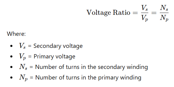
If a transformer has a primary voltage of 11 kV and a secondary voltage of 0.4 kV, the voltage ratio is:
Voltage Ratio=110.4≈0.036
5. Turns Ratio
This refers to the ratio of the total turns in the secondary winding to those in the primary winding of a transformer. Turn ratio is directly connected to the voltage ratio.
6. Vector Group
Represents the phase displacement between windings (e.g., Dyn11, YNd1), which is critical for parallel operation and system synchronization.
7. Cooling Class
Specifies the cooling method used, such as ONAN, ONAF, OFAF, or dry-type air cooling, which impacts transformer efficiency and thermal management.
Read deailed artcile: Cooling Methods of Transformer- AN, ONAN, ONAF and OFAF
8. Impedance
This represents the transformer’s resistance to the flow of electric current, known as impedance. Impedance defines the transformer’s opposition to current flow and affects fault currents, voltage drops, and parallel operation. It is commonly expressed as a percentage impedance, which indicates the percentage of the rated voltage required to produce full-load current when the secondary is short-circuited, or alternatively as an ohmic value.
9. Frequency Rating
Typically 50 Hz or 60 Hz depending on the regional power system standards.
10. Tap Changer / Tapping Range
Off-load or on-load tap changers allow adjustment of voltage levels to regulate output under varying load conditions.
11. Insulation Level
Determines the maximum voltage stress the transformer can withstand, protecting against electrical breakdowns.
12. Temperature Rise Limits
Specifies the allowable temperature increase for windings and cooling oil, ensuring safe operation and longevity.
13. Efficiency
This represents the ratio of the transformer’s output power to its input power, commonly referred to as efficiency. It reflects how effectively the transformer converts electrical energy from the primary circuit to the secondary circuit with minimal losses.
14. Voltage Regulation
This refers to the variation in secondary voltage when the transformer load changes from full load to no load, expressed as a percentage of the no-load voltage. Known as voltage regulation, it indicates the transformer’s ability to maintain a stable and consistent output voltage under varying load conditions.
Read detailed artcile: Transformer Ratings- Formulas and Solved Problems
Power Transformer vs Distribution Transformer
Power transformers and distribution transformers are both essential components of the electrical system, but they differ in purpose, design, and application.
| Feature | Power Transformer | Distribution Transformer |
| Primary Use | Used in generation, transmission, and high-voltage networks to step up or step down voltage. | Used in the distribution network to supply electricity to end consumers at usable voltages. |
| Voltage Level | Operates at high voltages (typically above 33 kV). | Operates at lower voltages (typically below 33 kV). |
| Power Rating | High power ratings, usually in MVA. | Lower power ratings, typically in kVA. |
| Frequency of Operation | Continuous operation with high efficiency under varying loads. | Operates under relatively stable loads; efficiency varies with load. |
| Cooling Method | Often oil-cooled (ONAN, ONAF, OFAF) or sometimes dry-type. | Usually oil-immersed or dry-type, simpler cooling requirements. |
| Construction | Large and robust design to handle high voltages and currents. | Smaller and more compact to fit near consumption points. |
| Applications | Power plants, substations, transmission networks. | Residential, commercial, and light industrial supply. |
Applications of Power Transformer
Power transformers play a critical role in electrical systems and are widely used across multiple sectors for efficient energy transfer and voltage management. Key applications include:
- Power Generation: Power transformers step up the voltage produced by power plants before it is transmitted to the grid. This reduces current levels and minimizes line losses during long-distance transmission.
- Power Transmission: At different points in the transmission network, transformers step up or step down voltages to ensure efficient delivery, provide galvanic isolation, and enable impedance matching between circuits.
- Power Distribution: Transformers reduce high transmission voltages to levels suitable for residential, commercial, and industrial consumers. They also supply multiple voltage levels for varied applications, such as lighting, heating, cooling, and communication systems.
- Lighting Systems: Power transformers deliver low-voltage, high-current supply for lighting setups including fluorescent lamps, neon signs, and stage lighting, ensuring safety and consistent illumination.
- Audio and Signal Equipment: They are used to isolate, step down, or amplify audio signals in speakers, microphones, amplifiers, and other audio devices, providing clear signal transmission.
- Electronic Devices: Power transformers provide stable, low-voltage power to electronic equipment such as computers, televisions, radios, and communication devices.
- Industrial Machinery: They supply the required voltage and current levels for heavy machinery and motors in manufacturing plants, ensuring optimal performance and energy efficiency.
- Renewable Energy Systems: In solar and wind power installations, transformers step up or step down voltages to integrate generated energy into the grid efficiently.
- HVDC and Specialized Systems: Transformers are used in high-voltage DC systems and specialized industrial setups to provide voltage conversion, isolation, and protection.
Summary
A power transformer is a crucial component of modern electrical systems, ensuring efficient transmission, voltage transformation, and network stability. Its various types, advanced specifications, and wide range of applications make it indispensable in power generation, transmission, industries, and renewable energy infrastructure. Understanding how a power transformer works and where it is used helps in selecting the right design for reliable and long-term performance.
Related Articles: