In Electrical Engineering, Electrical Machines can be defined as machines that use electromagnetic forces and follow the laws of electromagnetic induction to convert either electrical power to mechanical power, e.g., Electric motors, or vice-versa, e.g., Electrical generators. Electrical motors and generators are categorized as electromechanical converters.
However, there is another category of electrical machines called Electrical Transformers. Transformers take electrical power as input and give the same amount of power as output (neglecting losses) at a changed voltage and current value. Electrical power is directly proportional to the product of the voltage and the current. A transformer alters the voltage and current levels in such a manner that the output power remains almost equal to the input power, neglecting the losses.
Electromechanical machines have rotating parts which are free to move. Electrical transformers, however, are static electrical machines, which means they don’t have rotating parts. That’s why these are not categorized as Electromechanical machines.
Let’s understand various electrical machines in brief.
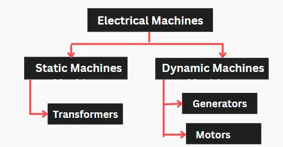
Types of Electrical Machines
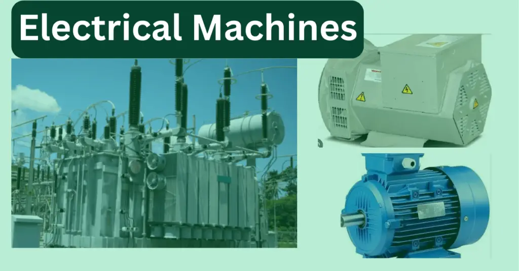
There are three main types of electric machines, namely transformers, generators, and motors.
Electrical Generators
Electrical generators are machines that convert mechanical power into electrical power as output. The basic principle of working of an electrical generator is based on the laws of electromagnetic induction, which says an electro-motive force (EMF) is generated in a conductor when it cuts a varying magnetic field.
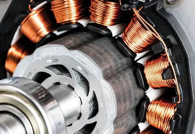
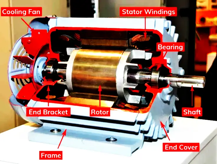
There are two possibilities for the generator to work – either the conductor remains at rest. At the same time, the magnetic field flux is in motion, or the magnetic field remains at rest while the conductor remains in motion. Under these two possibilities, the conductor will cut the magnetic field lines and generate an emf. There are two important parts of a generator – The stationary part called the stator and the rotating part called the rotor.
In electrical terms, the armature is the power-producing component, while the field is the magnetic field component of an electrical machine. Thus, in a generator, the armature can be on the stator or the rotor, and the same is true for the field. The magnetic field can be generated from a permanent magnet or with the help of electromagnets mounted on either a stator or rotor.
DC Generators
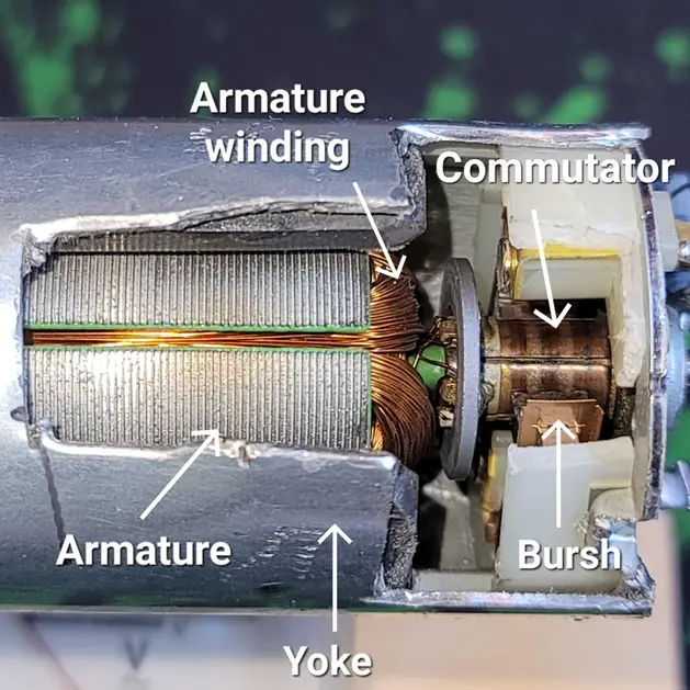
DC Generators, as the name suggests, are generators that generate DC voltage. Usually, the armature winding is on the rotor, while the field winding is on the stator in a DC generator. It consists of split rings (also called commutators) and carbon brushes. The commutator on the DC generator converts the AC into pulsating DC. It assures that the current from the generator always flows in one direction by reversing the direction of the current in the generator’s coil after every half-rotation. The brushes ride on the commutator and make good electrical connections between the generator and the load.
Read More: Types of DC Generators
AC Generators or Alternators
AC Generators generate alternating emf. In an AC Generator, the field winding remains on the rotor while the stator carries the armature winding. This is because the power requirement of field winding is much less compared to the power generated by armature winding. Also, the power generated is a three-phase power. If the rotor carries the three-phase armature windings, it will be much heavier, and the centrifugal force may lead to mechanical wear and tear. Slip-rings are used to supply the rotor field windings. In this case, only two slip-rings are required to supply DC power to the field. If the armature windings rested on the rotor, four slip-rings would have been required – three for the phases and one for the neutral.
AC generators are of two types: induction generators and synchronous generators.
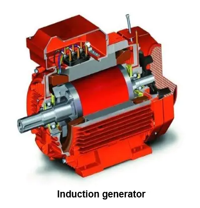
Induction Generators:
It is also known as an asynchronous generator. These generators use the principle of an induction machine to generate electrical power. The synchronous speed is defined as the speed at which the air-gap magnetic field flux rotates within the machine. It is given as
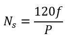
Where f is the frequency, and P is the number of poles. In an induction generator, the rotor tends to run faster than the synchronous speed, thus cutting the rotating magnetic field and generating electricity. Induction generators are used to generate electricity from wind turbines.
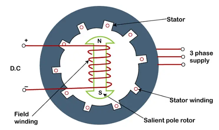
Synchronous Generators:
These are widely used to generate reliable three-phase AC power. In a synchronous generator, the rotor carries the field winding, which is supplied by a DC source. The rotor is made to rotate at the synchronous speed, which causes the stator armature winding to cut the magnetic field flux and generate three-phase power at a frequency corresponding to the synchronous speed.
Synchronous generators are widely used to generate electricity in various power stations, owing to their robustness and reliability. These are of two types: cylindrical rotor and salient pole.
Read More: Synchronous Generator
Motors
An electric motor is an electrical machine that converts electrical energy into mechanical energy. When a current-carrying conductor is placed inside a magnetic field, the conductor feels a force and gets deflected. This is the principle on which almost all electrical motors work.
DC Motors:
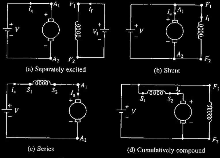
DC motors are direct reversals of DC generators. In fact, the same DC machine can work as a generator and motor. The field winding is supplied with a DC voltage, and the armature winding is supplied either by the same source or a different source. As a result, the current-carrying armature conductor feels a force inside the magnetic field generated by the field winding and begins rotation.
DC motors are of different types based on their configuration. A series DC motor is known for its universality (because it can work on AC current as well) and great speed-torque characteristics. A shunt motor, on the other hand, is known for its constant speed operations.
Read More: Types of DC Motors
AC Motors:
AC motors broadly are of two types: induction motors and synchronous motors.
Induction Motor:
An induction motor works at sub-synchronous speed. The rotor is short-circuited in nature, while the stator is supplied externally by a three-phase AC power. This power generates the rotating magnetic field (RMF), which is cut by the rotor windings. As the rotor windings are short-circuited, a current begins to flow through them, and it generates its own magnetic field flux. The rotor begins to rotate under the effect of both the magnetic field forces.
Read More: Induction Motor
Synchronous Motors:
Synchronous motors, on the other hand, operate at synchronous speed, hence the name. The stator armature windings are supplied by a three-phase AC source, which causes the generation of a rotating magnetic field. The rotor, however, is not short-circuited but is supplied externally by a DC source. This causes the generation of rotor magnetic poles, which are attracted by the opposite poles on the stator when aligned. As a result, the stator and the rotor poles lock with each other, and the rotor begins to rotate at a synchronous speed under the effect of the rotating air-gap magnetic field flux.
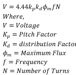
The relation between the voltage, frequency, and the number of turns in an AC machine can be deduced, and it is given as;
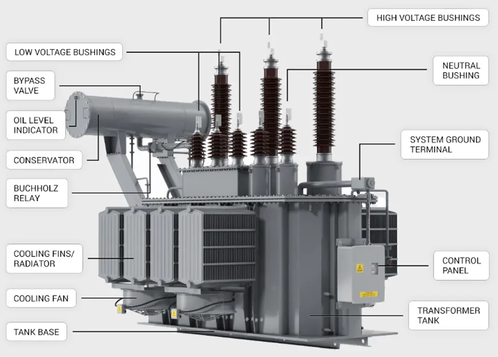
Transformers
Unlike motors or generators, which are dynamic machines, an ideal transformer is a static electrical machine that transfers input electrical energy at changed levels of voltage and current, keeping the power and the frequency constant.
Transformers are one of the most efficient electrical machines. This is because there are no rotational losses that a transformer is subjected to, like a motor or a generator. The power is transferred from the primary side circuit to the secondary side circuit, which is physically isolated but magnetically coupled. The number of turns on each side decides whether the voltage will be stepped up or down.
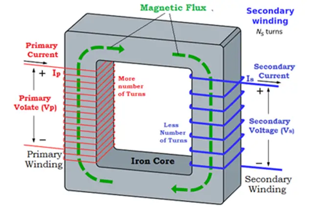
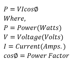
If the number of turns on the primary side or the input side is more than the secondary side, it is known as a step-down transformer, whereas if the number of turns on the secondary side is more than the primary side, it is known as a step-up transformer. As the power transferred remains constant, the output voltage in a step-down transformer goes down while the current goes. Similarly, in the case of a step-up transformer, the output voltage goes up while the output current goes down. This is because the electrical power is directly proportional to the product of the voltage and the current, and it is given as –
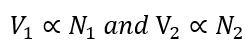
In a transformer, the maximum magnetic field flux and the frequency remain constant. Hence, we can say that the voltage on any side is directly proportional to the number of turns on that side.
Other Electrical Machines
Other electromagnetic machines include the Amplidyne, Synchro, Metadyne, Eddy current clutch, Eddy current brake, Eddy current dynamometer, Hysteresis dynamometer, Rotary converter, and Ward Leonard set.
Related Articles:
its a good explanation