A centre tapped transformer has a center tap on its secondary windings. The center tap divides the secondary windings into two equal parts, and it is located at the midpoint of the winding.
Construction of Centre Tapped Transformer
The centre tapped transformer has primary and secondary winding like a conventional transformer. The conventional transformer has one secondary winding, on the other hand, a centre tapped transformer has a secondary winding divided into two equal parts. Thus, the centre tapped transformer provide two equal voltage at its secondary winding.
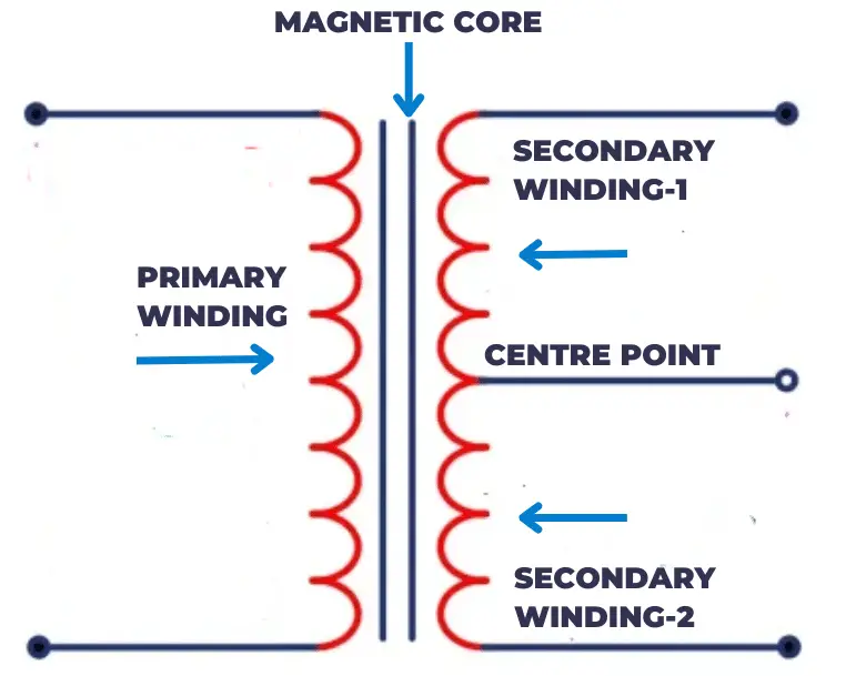
A tap is taken from the center of the secondary winding to create a centre tapped transformer. The center point is connected to a common ground which creates a reference point for both of the secondary winding.
The center point lies exactly on the center point of the secondary winding, and it divides the winding into two equal parts. Both parts of the secondary winding have an equal number of turns.
The primary winding has a larger gauge wire than the secondary windings because it handles higher voltage and current. Contrary to this, secondary windings have smaller gauge wires because they handle lower voltage and current.
The centre tapped transformer has an iron core made of laminated sheets of steel. The primary and secondary winding is wound on the core of the transformer. The laminated sheets reduce the eddy current losses and improve the efficiency of the transformer.
Working Principle
When the primary winding of centre tapped transformer receives alternating voltage, it draws current and produces magnetic flux. The magnitude of the magnetic flux produced in the primary depends on the number of turns and rate of change of magnetic flux.
The magnetic flux then travels through the low reluctance magnetic core and links to the secondary and primary winding of the transformer. According to Faraday’s law of electromagnetic induction, voltage is induced in the primary and secondary winding. The voltage induced in the primary opposes the mains supply and thus limits the inrush current. The linked magnetic flux produces two equal but opposite polarity voltages in both parts of the secondary winding.
Working of a Centre Tapped Transformer
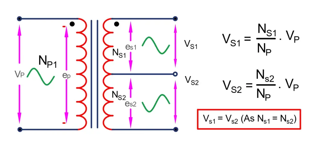
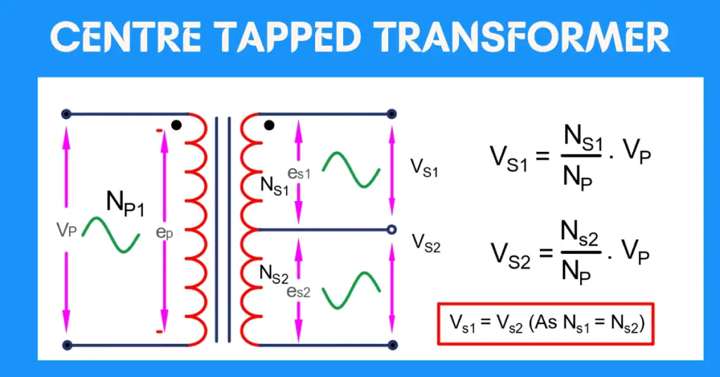
The winding arrangement and core of the transformer are given in the above image. When we feed the AC supply to the primary winding of the centre tapped transformer, it produces a varying magnetic field around it. The magnetic field cause magnetic flux set up in the core and the flux travels through the magnetic core and links to the secondary winding. The voltage is induced in the secondary winding as per Faraday’s law of electromagnetic induction.
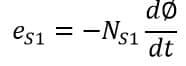
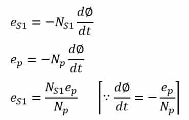
The voltage induced in one part of the secondary winding is:
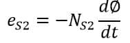
The voltage induced in the second part of the secondary winding is:
In the centre tapped transformer, the number of turns in both parts of the secondary winding is equal.
Therefore,
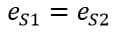
The magnitude of the voltage induced in both parts of the secondary is;
Similarly,
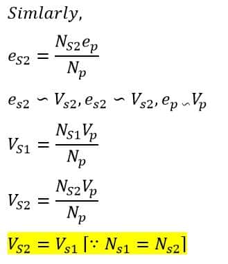
Difference between a Normal and a Centre Tapped Transformer
A normal transformer outputs a single voltage. However, a centre tapped transformer provides you with two or more voltages of equal magnitude depending on the tapping on the transformer. For example, a center tapped transformer of 240/24-0-24 volts rating will provide two equal voltages of 24 volts in magnitude with a phase shift of 180 degrees.
Applications of Centre Tapped Transformers
The following are the applications of centre-tapped transformers.
- Power Supplies: Centre tapped transformers provide two equal voltage outputs from a single transformer. It provides positive and negative supply, therefore it is used in operational amplifiers and other analog circuits that need a dual power supply.
- Rectifiers: With the use of Centre tapped transformers, it is possible to have full wave rectification of AC power to DC power. The rectifier diode is connected to two secondary winding that convert AC voltage to DC voltage
- Audio Amplifiers: The amplifier must provide a balanced output to have less noise and distortion in the signal. Centre tapped transformers are connected to the amplifier’s output stage to reduce noise.
- Isolation: Centre tapped transformers provide galvanic isolation, and therefore, they are used to isolate two electrical circuits to prevent electrical interferences.
it is good understandable explanation