The cascaded transformer is used for the generation of AC high voltage. AC high voltage is required for testing electrical equipment like transformers, cables, switchgear, capacitors, and insulators.
The cascaded transformer functions as a step-up transformer. The number of transformers is connected in the cascading arrangement to get the high voltage. Now, a question arises, when it is possible to get the high voltage with a single transformer, then why to use a number of transformers in a cascading connection to get the high voltage? Suppose, you want to get the 400 kV voltage from 230 Volts, then by choosing a transformer with a turn ratio of 1: 1880, you can get the desired voltage. However, in this case, the insulation required for the transformer will be very high, making the transformer costlier and heavy in weight. The cost of the insulation is squares of the voltage.
The concept of generation of high voltage with a single transformer is technically ok, but not economical, and moreover, it makes the high voltage generating set very bulky. Therefore, the cascaded transformer method for generating AC high voltage is the best method.
If we use the transformers in the cascading method, the insulation requirement will be less. This makes the transformer cheap. Also, the cascaded transformer unit becomes light in weight, leading to ease in erection and transport. For testing electrical equipment, we require high voltage and low current. The cascaded transformer is the most suitable for electrical equipment testing applications.
The cascaded transformers are mainly used for short-time high-voltage tests on electrical equipment. The typical current requirement for these tests is as follows.
| Electrical equipment | Current Requirements(Amps.) |
| Insulators, Circuit breakers and bushings | 0.1 -0.5 A |
| Power Transformer | 0.5- 1.0 A |
| Cables | 1 A and above |
Now, let us discuss the working of a cascaded transformer.
Working of Cascaded Transformer
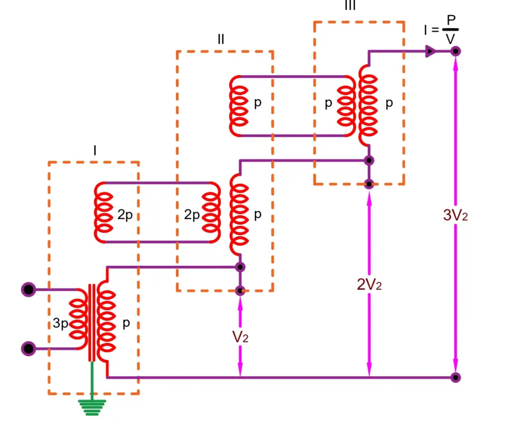
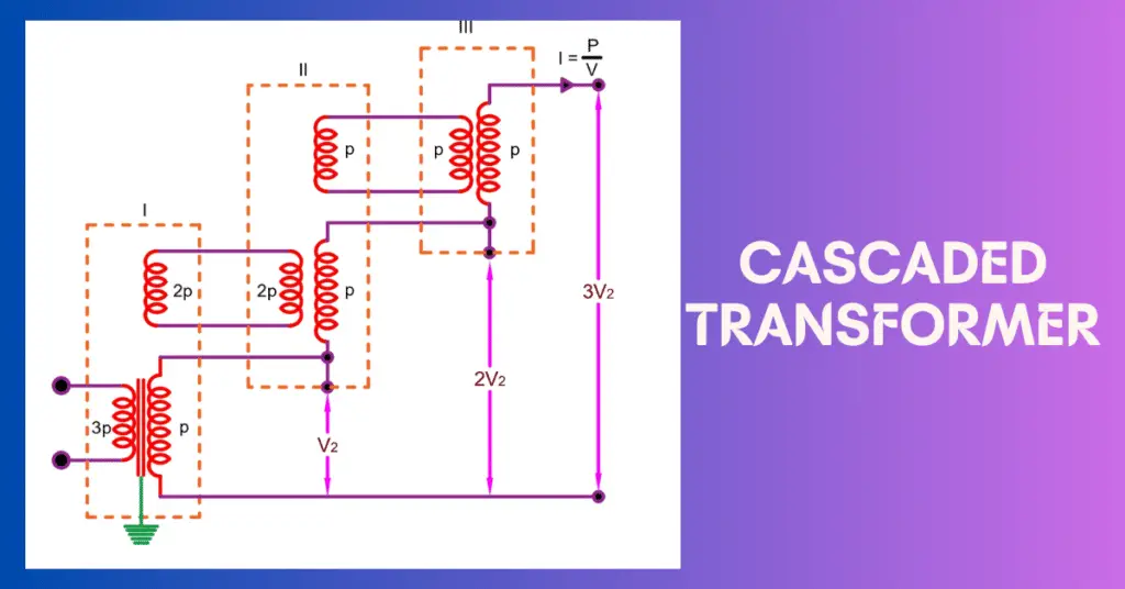
The above circuit shows the cascading of three transformers. The dashed line shows the set of cascaded transformers. The transformer tank and the core of the first-stage transformer are grounded. The tank of the second and third-stage transformer is not grounded. and suitable insulation is provided between the second and third-stage transformer.
The low voltage Let V1 is fed to the primary of the first stage transformer. The first stage transformer steps up the primary voltage according to the turn ratio of the transformer. The secondary voltage of the first stage of the transformer is V2. Thus, we get voltage V2 voltage between the terminal of the secondary of the first stage transformer and ground.
The secondary of the tertiary winding is connected to the primary winding of the next stage transformer in the series connection. The primary of the second-stage transformer receives the same voltage as the first-stage primary receives, therefor the secondary voltage of the second-stage transformer will be equal to V2. Thus, we get the V2+V2= 2 V2 voltage between the the terminal of secondary of the second stage transformer and ground.
Further, the primary of the third-stage transformer receives the same voltage as fed in the primary of the first and second-stage transformers. Thus, the primary of the third stage transformer receives the same voltage as the first stage and the secondary stage primary receives, therefore the secondary voltage of the third stage transformer will be equal to V2. Thus, we get the V2+V2 +V2= 3V2 voltage between the the terminal of secondary of the third stage transformer and ground.
It is to be noted that the last stage transformer has two-winding and the transformer before the last stage has three- three-winding transformers. If there are four stages, then the transformers of the first three stages have three-winding and the transformer of the last stage has two-winding.
The tank of the second and third-stage transformers are at potential V2 and 2V2, respectively above the earth, therefore they need adequate insulation. The connecting leads from the tertiary winding and high voltage winding are connected to the next stage transformer through bushings.
However, if we use mid-point potential type high voltage winding, then the potential at the tank will be 0.5V2, 1.5V2, and 2.5 V2 respectively for three stages, leading to cheaper construction because now the high voltage insulation requirement is for V2/2 tank potential.
Loading on Cascaded Transformer
The total apparent power VA of the cascaded transformer shown in the above pic is 3 V2 I= 3P. Each secondary winding of the transformer carries a current I=P/V2. The loading on the winding of each transformer is shown by the letter P in the figure. The loading on the primary of the third-stage transformer is P. The loading on the primary of the second and third stage transformer is 2P and 3P respectively. Thus, the primary of the first stage transformer has maximum loading. Therefore, while designing a transformer the loading factor must be considered.