Industrial Automation Pre-engineering Design Documents comprise Documents related to Control Index, Material Control Index, Project Schedule, Commissioning, Pre-Commissioning Site Survey, P&ID Diagram, and Process Flow Diagram.
There are many automation documents in an industry. These are classified into different categories based on the technical requirements and project life cycle such as:
- Project and General Documents
- Process Documents
- Electrical Documents
- Instrumentation Documents
- Quality Documents
- Project Documents
Project and General Documents
Project and general documents are made when the project is in the scheduling stage. The project and general documents consist of various stages like the design of the machine, material management, GA drawing approval, electrical drawings submission and their approval, erection, and commissioning team manpower deadlines, electrical panel manufacturing, software development, FAT by engineers, and final dispatch.
When the dates of the project are decided, then these documents will help in the proper and timely execution of a project. Each project stage should be completed within a set time. This is necessary for the completion of the project. These documents have multiple documents. They are:
1. Document Control Index
2. Material Control Index
3. Project Schedule
4. Commissioning
5. Pre-Commissioning Site Survey
6. P&ID Diagram
7. Process Flow Diagram
Let us look into each of these in a detailed way. The followings are the documents that are parts of Industrial Automation Pre-engineering Design Documents.
1. Document Control Index
The document control index is one of the main documents in the preparation of a project. It is a means of linking all digital documents with some attributes or labels. In a project, there are many document parts. So, it is difficult to know which document is related to which subject and what its meaning is.
Hence, a document control index is used in every document for identifying the type and purpose of the document. The document control index makes the discovery of files easier and so allows the user to access any document at any moment with a few clicks. When proper indexing is done, then proper arrangement into sub-folders is possible according to the categories.
A simple example can be tagging a document. The tagging is based on the client name, consultant name, date, purchase order number, and the heading title (which shows the type of document). When the project is being designed, this index is a must for pointing to various types and meanings of them.
2. Material Control Index
A project needs a supply of materials and when there is no control over it, then the project is a waste of time. The material control index is a special document that will help in dealing with the problem mentioned above. It would start from procurement and will last till the last usage stage.
Material Control Index document generally includes purchasing/procurement of materials, the receiving of materials, inspection of materials, storage of materials, issue of materials, maintenance of material records and materials, and/or stock audit.
When a proper idea of the material control index is understood, then only it can be committed to the customer as to how much time it will take for a project to complete. Material control index would help in uninterrupted protection by continuous availability, minimum wastage and loss of materials, financial control, less delay in production, and high-quality assurance and efficiency. Material control index documents should be available in hand before taking on any project.
3. Project Schedule
There must be proper dates decided with the customer in the completion of a project. Each and every project has many stages the design of the machine, material management, GA drawing approval, electrical drawings submission, and their approval, commissioning team manpower deadlines, electrical panel manufacturing, software development, FAT by engineers, and dispatch.
If the dates of the project are approximately decided between the vendor and customer, it will help in the proper and timely execution of a project. Each project stage should be completed within a set time limit. This will ensure the completion of the project eventually. Thus, it is important to maintain the project schedule with the customer before taking the order in hand.
4. Commissioning Schedule
When the project schedule is decided, it is important to share a commissioning schedule with the customer. The commissioning schedule would contain information related to the project completion date, material received at the site, commissioning team arrival dates, pre-commissioning activities start (for example, utility, mechanical and electrical), commissioning activities, and operational readiness. Although these dates are not always actual, they must be met tentatively which will help in the successful completion of the overall project.
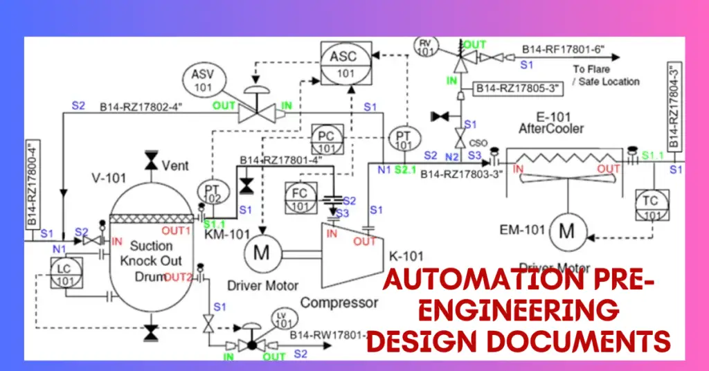
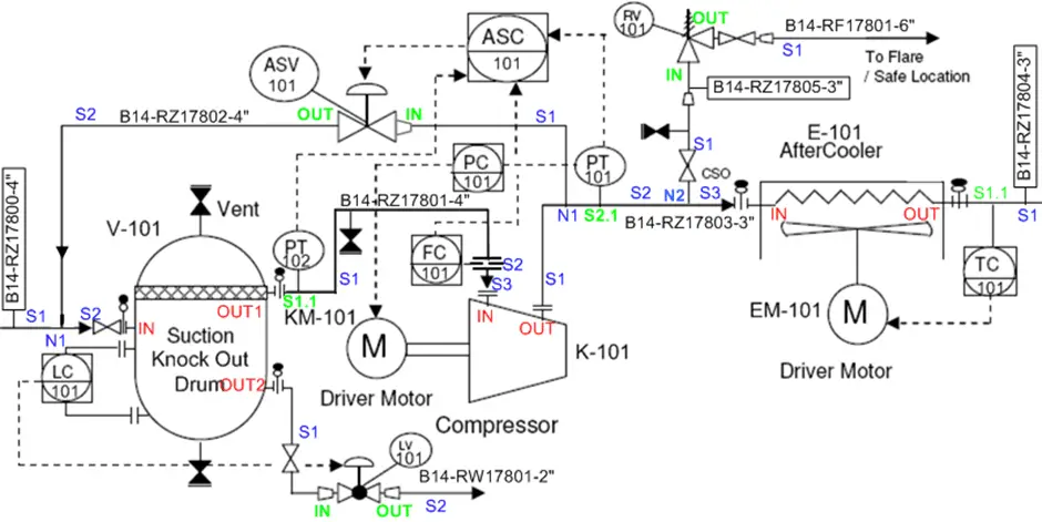
5. P&ID Diagram
The P&ID diagram stands for pipeline and instrumentation diagram. The P&ID diagram basically gives an overall look at a detailed piping, instrument location, tank location, utility transfer source, and destination and construction process. After the client requirements are understood and the possibilities are conveyed, the design of P&ID is possible.
The P&ID diagram helps to understand how the process will look like, flow, and the complete overview of the plant. The P&ID diagram is an important document for programmers also, as it is necessary to understand the process flow. The P&ID diagram would help in designing the program accordingly.
The P&ID diagrams are useful in the following ways:
- The P&ID diagram is useful in evaluating construction processes.
- It is useful in serving as a base for control programming.
- Useful in developing guidelines and standards for facility operations
- Useful in producing documents that explain how a process works
- The P&ID diagram is useful in providing a common language for discussing plant operations.
- It is useful in creating and implementing philosophies for safety and control.
The P&ID diagrams have some limitations. They are:
- The P&ID diagram is a graphical representation of processes; hence, they cannot be relied on as real models. This is because they may not be drawn to scale or geometrically accurate.
- The P&ID diagram does not have a universal standard so they may be different within the same plant also.
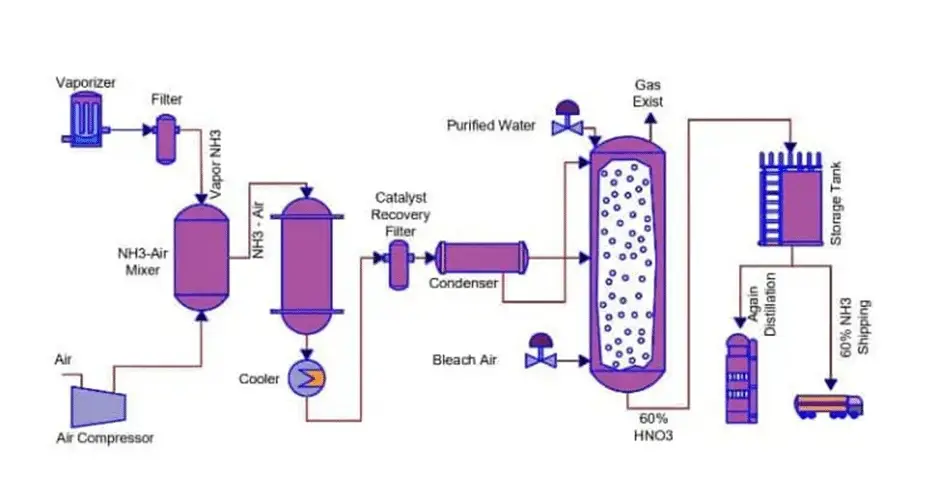
6. Process Flow Diagram
The process flow diagram is also called the parent of P&ID diagrams. The P&ID diagram is designed based on the process flow diagram. The process flow diagram is a type of flowchart that shows the relationship between major components at an industrial plant. When the flow of the process is known from start to end, then the system can be easily designed.
A series of symbols and notations are used for depicting a process. The complexity of the diagrams can vary from very simple to complicated depending upon the maker of the diagram, the software used, and the process complexity. These symbols vary in different places.
The process flow diagram has the following purposes:
- The process flow diagram is usually used to show a process such that it is better understood, gives quality control, and can be used for the training of employees.
- It is used for standardizing a process for optimal efficiency and repeatability.
- The process flow diagram is used to study a process for efficiency and repeatability.
- It is used for modeling a better process or creating a brand-new process.
- The process flow diagram is used to communicate and collaborate with the diagrams which show the various roles in an organization or the outside of it.
A process flow diagram includes the following elements:
- Major equipment: Names and ID numbers. For example, compressors, vessels, mixers, pumps, boilers, coolers, etc.
- Process piping: it moves the product, generally fluids, between equipment pieces.
- Process flow direction
- Control valves and process critical valves
- Major bypass and recirculation systems, etc.
This is all about Industrial Automation Pre-engineering Design Documents.