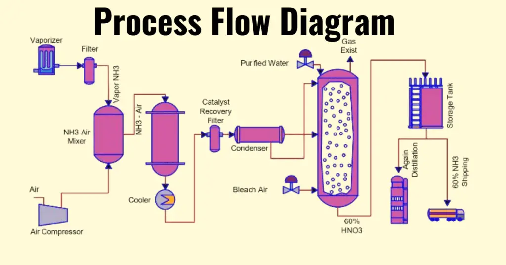
Process Flow Diagram (PFD) is a drawing depicting how the process is happening in a process plant. It highlights only the major equipment/instruments installed in a plant. It doesn’t contain each and every piece of equipment. Hence we can say that it is not much in detail as compared with Piping and Instrumentation diagram (P&ID). In this article. We will study later in the article what’s included and what’s excluded in a Process flow diagram.
History
The first person who developed a flow process chart was Frank Gilbreth Sr. in the year 1921, when he introduced it to the American Society of Mechanical Engineers (ASME).
Later, the industrial engineering, manufacturing and even business sectors adopted this concept in the form of business process diagrams, data flow diagrams, information processing & other chart types.
Process flow diagram(PFD)
A Process Flow Diagram (PFD) is a type of flowchart that shows the relationships between major components in a process. There is a wide use of it in chemical engineering and process engineering.
We sometimes call Process flow diagram as Process Flow Chart, Flowsheet, Block Flow Diagram, Schematic Flow Diagram, Macro Flowchart, Top-down Flowchart, System Flow Diagram or System Diagram or System Diagram on the basis of its use in the industry. Underneath is a process flow diagram example.
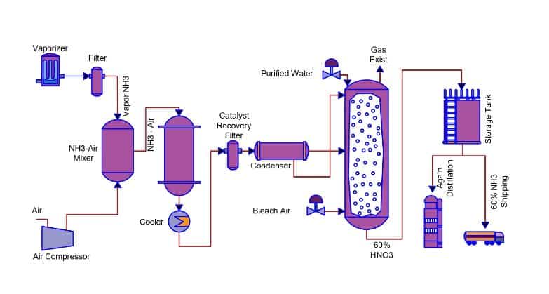
We mostly use process flow diagrams in a process plant such as Power plant, Oil & Gas plant, Petrochemical industry, Fertilizer plant etc. It is also suitable for a small industry such as a Sugar plant.
Various symbols and notations in a process flow diagram depict and illustrate the process. It is very easy to understand the symbols because the symbols are very simple. The main idea of a Process flow diagram is to demonstrate the process with the help of some shapes and codes in the easiest way possible by including the basic process information.
A PFD does not show the minor details of the process, rather it focuses on the equipment used, control valves and other major instruments.
What is the Purpose and benefits of PFD?
A process flow diagram helps in understanding the complete overview of the operating system. We can use a PFD to find the material flow through the unit.
- Documentation- A PFD document a whole process, and thus it enables the better process understanding , quality control and training of employees.
- To make a standard process for optimal efficiency and repeatability.
- To study a process for better efficiency improvement. It also helps to know the bottlenecks and other deficiencies.
- To make a better process or to create a new process.
- To make a better communication and collaboration system with diagrams that tells to various roles in the organization or outside of it.
A PFD is a main documents that we use to draw the Plot Plant and P&ID.
What are included in a process flow diagram?
As already discussed a PFD contains only the major equipment’s/process and instruments. PFD is usually not in much detail, for more detail information about the process and plant we generally consider Piping and instrumentation diagram. Now we will discuss what PFD includes.
- Major Equipment– Compressors, mixers, vessels, pumps, boilers and coolers etc. are the major equipment in a process plant, and hence PFD includes all these equipment and also highlights with a certain symbol. It includes the tag numbers of major equipment.
- Process Piping – A process flow diagram highlights the major pipelines through which the process fluid/gas moves.
- Operational Data – A PFD highlights the important and major process parameters such as pressure, temperature, density, mass flow rate and mass-energy balance. It contains the minimum, normal and maximum values & the equipment specifications.
- Process flow direction– It provides the process flow direction of all the process lines. A arrow on PFD shows the direction of the flow.
- Control valves and process-critical valves– A PFD highlights the major valves.
- Recirculation system
- Major bypass system
- Composition of fluids – A PFD also shows body fluid composition, intracellular fluid composition, extracellular fluid composition & transcellular fluid composition
- Process stream naming– A PFD lists the process stream names.
- Connections with other systems
What are not included in a PFD?
The followings are not a part of PFD.
- Piping specification and piping codes– A PFD does not cover the Pipeline specification codes and related information.
- Process control instruments– A PFD highlights only main instruments that controls the critical process parameters.
- DCS/ESD logic– Any logic related to tripping or shutdown are not a part of a PFD.
- Minor bypass values
- Isolation and shutoff valves
- Maintenance vents and drains
- Relief valves and safety valves
- Code class information
However, all the above points are parts of a Piping & Instrumentation diagram (P&ID).
How to Plan and Create a Process Flow Diagram?
There are following steps for the creation of a PFD.
- Define the scope of the process- Purpose of study & its outcomes.
- Types of details for creation of a PFD
- Study equipment, related data & activities with the help of observations & interviews,
- Draw a rough sketch.
- Discuss with your team for suggestions.
- Make a draft and seek approval from process experts.
- Now, your process flow diagram is ready & you can use it.
Block Flow Diagram
When the diagram needs to show several processes happening in a plant, we need to consider Block flow diagram. It is very concise and generally gives an overview of the entire process, containing very less detail. These are called as Block Flow Diagrams or Schematic Flow Diagrams. Each block can represent a single piece of equipment or a stage in a process. A rectangle is usually used to display a piece of equipment and labels illustrate function. Below is a typical BFD of a process plant.
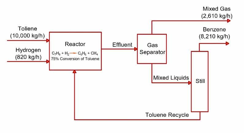
A block flow diagram gives the overview of a plant and hence, doesn’t contain as much information as it’s available on a Process Flow diagram. Based on the amount of information contained in a diagram we discussed till now, we can conclude that-
Piping & Instrumentation diagram (P&ID) > Process flow diagram (PFD) > Block flow diagram (BFD)
Uses of PFD
Some of the main usage of a PFD are as follows.
- As the PFD does not contain much detail information and generally the codes and symbols are very easy to read and understand, it is very useful for plant engineers, new joiners, vendors to get an overview of the entire facility which otherwise would have been very difficult to understand.
- Due to ease of understanding of PFD, it is also used for process improvement, HAZOP study, job safety analysis & tool box talk etc.
- It is used as a reference to prepare the piping & instrumentation diagram (P&ID).
Read Next: