This article describes charging Current in Transmission Line. Two conductors with opposite charges separated by a dielectric medium are called capacitors and this phenomenon is known as capacitance. The same phenomenon happens in the transmission line. The capacitance forms between the conductors & between the conductor and the earth as well.
The charging current in a Transmission line is caused by a pure capacitance effect. When there is a potential difference across the sending end of the transmission line, current starts flowing in the conductors as in a capacitor. The current leads the applied voltage and this leading current is called the charging current in the transmission line.
In a transmission line, air acts as a dielectric medium between the conductors. The capacitance of a transmission line is constant for the length of the line and spacing among the conductors. One important thing is that the Charging current flows in the transmission line even when the line is not loaded. At no-load conditions, the transmission line draws a leading current to that of the applied voltage.
The charging current drawn is in quadrature with the applied voltage and is independent of the load. The effect of the charging current can be observed only on the transmission lines having a length of over 100km. In other words, the capacitance of the transmission line increases with an increase in the length of the transmission line.
The charging current drawn by the capacitance of the line depends on the parameters mentioned below:
- The magnitude of the supply voltage
- The capacitance of the line
- Operating frequency of the line
Modeling of Shunt Capacitance of the transmission line
There are two ways of modeling an overhead transmission line. In both models, the line consists of series resistance (R), series inductance (XL), and shunt capacitance (XC).
The entire shunt capacitance in T-model is assumed to be lumped in the middle of the line and half of the line resistance and reactance is on either side.
In the π-model, in which the series impedance of the line is in the center and the shunt capacitance is divided into two equal parts on either end of the line.
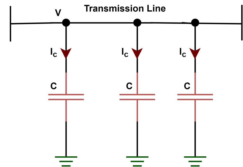
In a typical three-phase power system, because there are potential differences between the phase conductors and between each phase conductor and ground, each conductor exhibits self-capacitance between itself and the ground and mutual capacitance with regard to other conductors.
Approximate charging current for various overhead transmission line
The below-given table shows the approximate charging current values for various overhead transmission line voltage levels.
| VOLTAGE LEVEL | CHARGING CURRENT(A/mi) |
| 765 kV | 3.10–3.20 |
| 525 kV | 2.05–2.20 |
| 345 kV | 1.35–1.45 |
| 230 kV | 0.90–0.98 |
| 115 kV | 0.45–0.50 |
Charging Current Formula
Charging current for a single-phase line is;
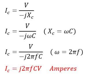
Where,
C= line-to-line Capacitance in farads
Xc= Capacitive reactance in ohms
V= line voltage in volts
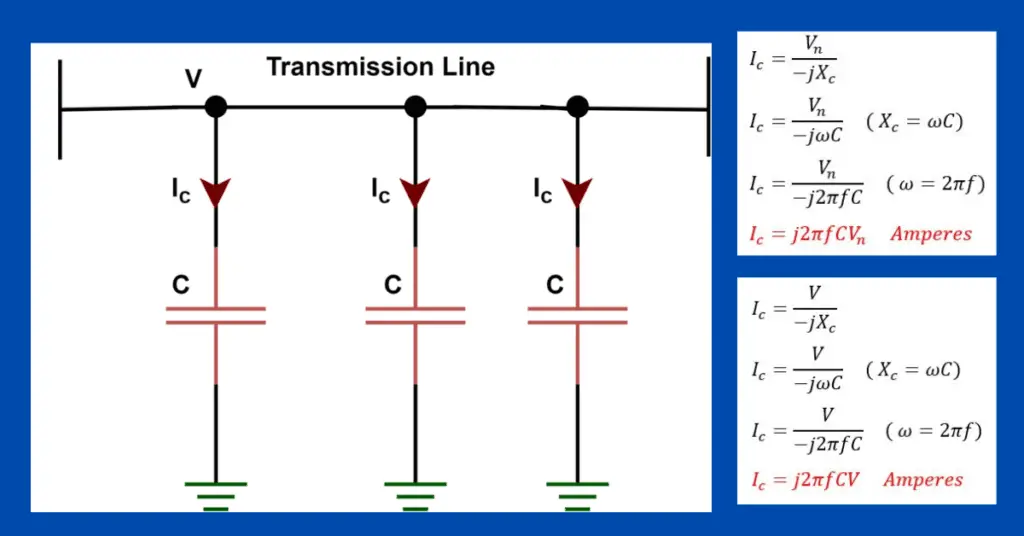
Charging current for a three-phase line is;
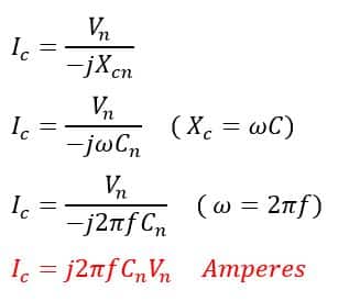
Where,
Cn= Capacitance to neutral in farads
Xc= Capacitive reactance in ohms
Vn= Phase voltage in volts
Charging Voltamperes of Transmission line
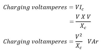
Charging voltamperes for a single-phase line is;
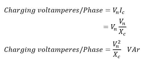
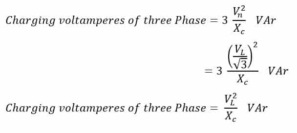
Charging voltamperes for a three-phase line is;
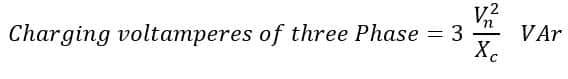
Total three-phase charging voltamperes is
Charging voltamperes in terms of line voltage is
Power Loss Due to Charging Current
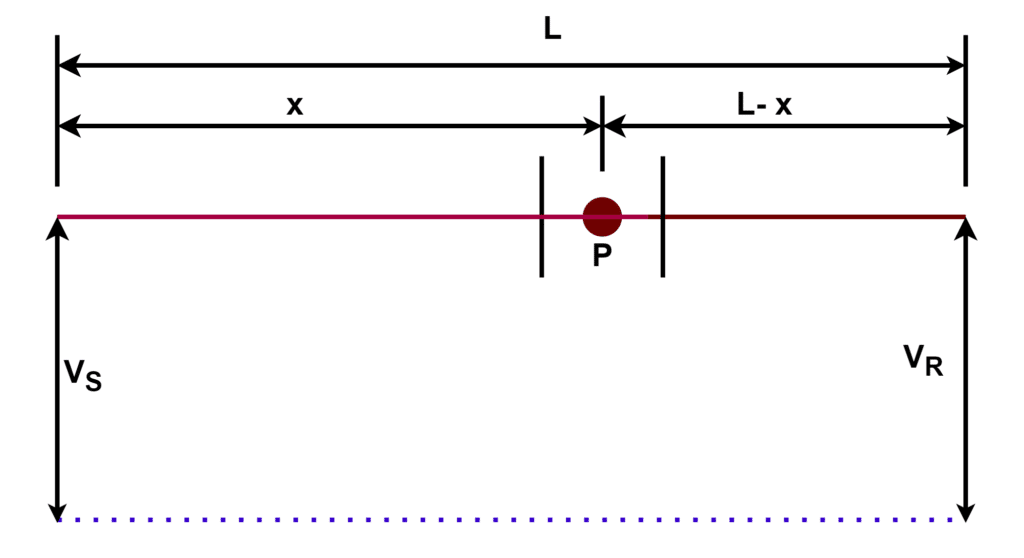
Let us consider a line of length L km having a charging current Ic at the sending end. Take a point P at a distance of x km from the sending end of the length L km;
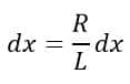
The total resistance of the transmission line is R, so the per unit resistance of the line is R/L.
Therefore, the resistance for the small element is,
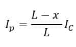
The charging current at the point P is
We can calculate the loss in the small element
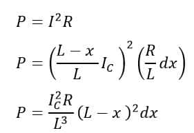
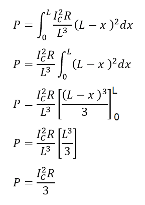
Therefore, total power loss in the entire line length L due to charging current is,
Solved Problem on Charging current of Transmission line
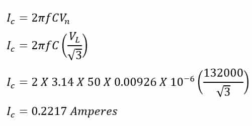
3-Ph 132kv 50Hz overhead line has ACSR conductors and a capacitance of 0.00926µF/km. Find line charging current.
Given data
Vph-ph(V-line)=132000V
f = 50 Hz
C= 0.00926µF/km