In this article, we will discuss how a 4 -20 mA transmitter works. A sensor measures the parameters like temperature, pressure, flow, or level. The electronics part of the transmitter converts the signal received from the sensor to a suitable form as per the design of the transmitter.
The most common type of transmitter output is a 4 to 20 mA signal. Other signals like Foundation Fieldbus, and Profibus are also available, but 4 to 20 mA signal is widely used. The signal is used by a system like PLC or DCS.
4 to 20 mA Transmitter
A transmitter is an electronic device that converts the signal received from the sensor to a suitable form. 4 to 20 mA transmitter is widely used in almost all industries. All 4 to 20 mA transmitters are loop-powered transmitters. Every transmitter has a dedicated loop through which they communicate with the system for transferring the signal to the system.
4 mA represents the low value of the span configured for the transmitter. While 20 mA represents the high value of the span configured for the transmitter. 4 mA is chosen to have a live zero in the system. This live zero will detect any cable failure or loop fault.
Suppose a temperature transmitter is used for measuring the temperature of a furnace. The range configured for the temperature transmitter is 0°C to 1000 °C. So, at 0 °C, the output from the transmitter will be 4 mA. While at 1000 °C the output of the transmitter will be 20 mA.
The 4 to 20 mA transmitter requires 24 VDC with 20 mA current as per standard. Generally, the current is always more than 20 mA supplied by the system. The transmitter then manipulates the mA as per the process variable.
Let us see how will transmitter will respond to different inputs from the sensor.
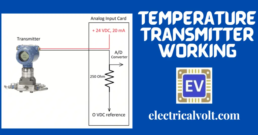
Transmitter and Analog Input Card Connection
As shown in the figure, the transmitter is supplied 24 VDC from an analog input card. In the negative loop cable, a 250-ohm resistor is used. The purpose of this resistor is to convert the mA received from the transmitter to a voltage in the range of 1 V to 5 V.
If the current is 4 mA, then as per ohm’s law,
Voltage(V) = Current(I) * Resistance(R)
V = 4 mA * 250 Ohm
Voltage(V) = 1000 mV = 1 Volt
Similarly, for 20 mA, the voltage is 5 Volt
Let us see some cases for the temperature transmitter with its operation in the 0 °C to 1000 °C range.
Case 1: Process variable is 0 % i.e. 0 degree Centigrade
The transmitter’s output will be 4 mA when the transmitter will receive 0 °C as input from the sensor which may be an RTD or a thermocouple. This value corresponds to 0 % of the configured span. So, in this case, the voltage will be 1 Volt as we saw in the calculations.
Case 2: Process variable is 25 % i.e. 250-degree Centigrade
The transmitter will deliver an output of 8 mA corresponding to an input of 250 °C from the primary temperature sensing element. This value corresponds to 25 % of the configured span. So, the voltage will be 2 Volt across the 250-ohm resistor.
Case 3: Process variable is 50 % i.e. 500-degree Centigrade
The transmitter will deliver an output of 12 mA corresponding to an input of 500 °C from the primary temperature sensing element. This value is 50 % of the configured span. So, the voltage will be 3 Volt across the 250-ohm resistor.
Case 4: Process variable is 75 % i.e. 750-degree Centigrade
The transmitter will deliver an output of 16 mA corresponding to an input of 750 °C from the primary temperature sensing element. This value corresponds to 75 % of the configured span. So, the voltage will be 4 Volt across the 250-ohm resistor.
Case 5: Process variable is 100 % i.e. 1000 degree Centigrade
The transmitter will deliver an output of 20 mA corresponding to an input of 1000 °C from the primary temperature sensing element. This value corresponds to 50 % of the configured span. So, the voltage will be 5 Volt across the 250-ohm resistor.
The transmitter generates different mA for different inputs from the primary sensing element. The mA remains in the range of 4 to 20 mA when the process variable is within the configured span. The mA keeps on changing as per the input from the primary sensing element and thus produces different mA.
What are the main advantages of a 4 to 20 mA loop?
One of the most important advantages of using a 4 to 20 mA loop-powered transmitter is that the zero is live here. So, in case of any cable failure or loop fault, we can quickly identify the failure. The transmitters working on 4 to 20 mA requires a single pair of cable.
A twisted pair cable is used for 4 to 20 mA current transmission. The twisted pair cable cancels out the electrical noise which is very important in transferring the data to the system. Also, the 4 to 20 mA loop does not require any other cable for powering ON the transmitter as in the case of a 3-wire and 4-wire system.
Also, the advantage of using 4 to 20 mA is that the current signal does not drop as the voltage signal does.