Definition: Winding Factor is the product of the Distribution factor (Kd) and the coil span factor (Kc). The main purpose of the winding factor is to improve the rms generated voltage in a three-phase AC machine.
Now question arises why we need to keep winding factor.The answer is the winding factor makes the output voltage almost sinusoidal free from harmonics. As a result, the improved voltage makes the electrical machines generate constant torque. As we all know, the torque is proportional to the square of the RMS AC voltage.In addition to this, it reduces the harmonics in the system, lower the losses and improves the machine efficiency.
The resultant voltage depends on the distributed winding and the coil span. The distribution of the winding and coil span factor decides the winding factor. The winding factor is denoted by the Kw.
The EMF equation is given below:
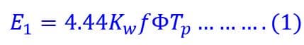
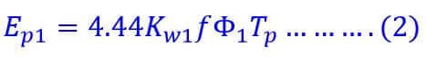
The induced voltage in the winding is non- sinusoidal because of non-sinusoidal flux density distribution. For individual harmonics order, the coil span factor, distribution factor, and winding factor will be different. EMF per phase is given below.
EMF per phase for 3 rd order harmonic is ;
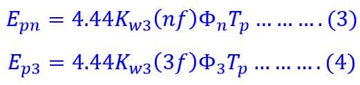
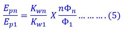
The ratio of the n th harmonic order phase voltage to fundamental phase voltage is given below.
Therefore,
Where,
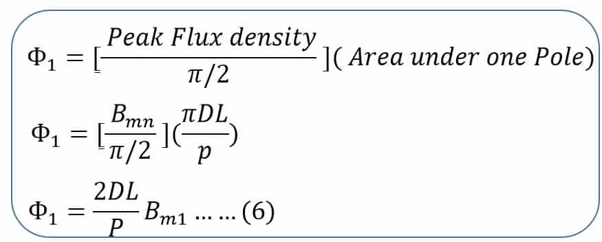
- ϕ1 is the total fundamental flux per pole.
- ϕ1 = average flux density x area under one pole
Where,
- Bm1 is the peak value of the fundamental component of the flux density wave
- D is the mean diameter of the armature
- L is the armature axial length
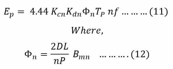
Similarly for the nth harmonic
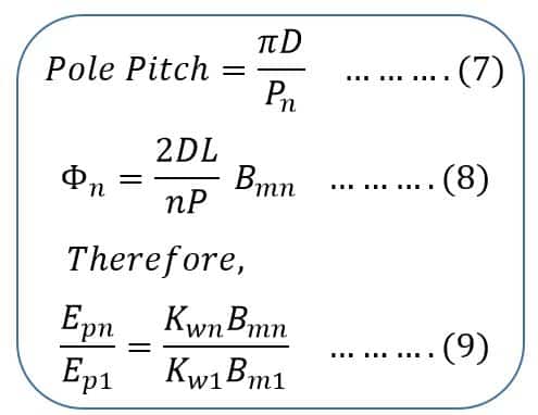
Where,
Bmn is the peak value of the nth harmonic flux density
Winding Factor for nth order Harmonic
The winding factor corresponding to the nth harmonic voltage is given as:
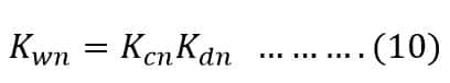
Where Kcn and Kdn are the coil span factor and distribution factor for the nth harmonic.
Therefore, the nth order harmonic induced EMF per phase is given by the equation shown below:
The induced voltage in the winding contain harmonics because of non-sinusoidal flux distribution. If we analyze the induced voltage waveform, it has odd harmonics. The even harmonic order is absent because voltage waveform is symmetrical about x- axis. Thus, the phase voltage has 3rd, 5th, and 7th harmonics.
The star connected synchronous generator does not have 3rd harmonics because all three phase voltage are in the same phase and have the same magnitude. Thus the 3rd order harmonic and multiples of 3rd order harmonic is absent in star connected alternator.
The magnitude of current of lower order harmonic is more compared to the higher order harmonic. The magnitude of harmonic order voltage reduces with an increase of harmonic order. Therefore,5th and 7 th harmonic order is predominant and proper care of its reduction at design stage is must. The 5 th and 7 th order harmonics are known as Belt Harmonics.
The RMS valve of line voltage of the star connected alternator can be expressed by below-given equation.
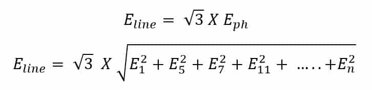
Where, subscripts 1, 5, 7, 11 denote fundamental,5th order,7th order,11th order harmonic voltage.
Read Next: