We will discuss the basics of resistance temperature detectors (RTD) in this article. The resistance temperature detector is one of the most common devices used for temperature measurement in industries. The Resistance Temperature Detector is commonly known as RTD.
We use RTDs in a variety of applications, from industrial manufacturing and testing to power plants, automotive engines, cold storage, and washer dryers. RTD consists of a metal wire to measure temperature. It is available in a variety of configurations. Thus, it is possible to choose the RTD for a wide range of temperature measurements for various processes.
A change in temperature will create a change in resistance of RTD i.e. a rise in temperature will increase the resistance of the RTD. The changed resistance is used to determine the temperature. This relationship between RTD and temperature is directly proportional and hence RTD is said to be having positive temperature coefficient.
RTD has sensing metal made up of Platinum (the most commonly used one), gold, silver, nickel, or copper.
The resistance of the RTD varies in proportion with temperature as formulated below
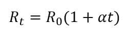
Where
Rt = resistance at temperature t degree centigrade
R0= resistance at temperature 0 degree centigrade
α = temperature coefficient of RTD (Per degree centigrade)
t = temperature
For example, PT100 is used and resistance is 110 ohms. “α“ for PT100 is 0.00385 per°C
As per the formula,
110 = 100(1+0.00385 * t)
Solving the above equation for “t“, we get
t = 25.974 °C
The above formula can be used to determine the resistance also for a given temperature which is mainly used while calibrating RTD.
The most common type of RTD used is PT100.
What is PT100?
PT100 means the resistance of a Platinum wire of RTD at 0°C. Here, PT is platinum, and 100 is the resistance at 0°C. Similarly, for other metal RTD, Cu10 means the resistance of Copper wire RTD is 10 Ω at 0°C. Ni120 means the resistance of Nickel wire RTD is 120 Ω at 0°C.
Types of RTD on the basis of its element construction
We can classify the RTD on the basis of its element construction.
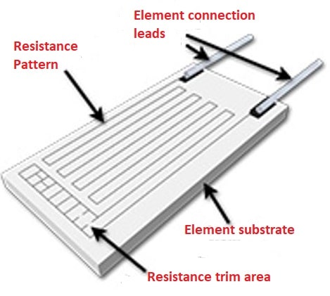
Wire Wound RTD
In a wire wound RTD, a resistance wire is wound around a nonconducting core, which is usually made of ceramic. The sensor is carefully trimmed in terms of length to achieve the specified resistance at 0°C. This is called the “R0” resistance. The lead wires are attached to the resistance wire, and then a glass or ceramic coating is applied over the wire for protection. As the temperature rises, the length of the resistance wire increases slightly. In the design, care must be taken to ensure that the resistance wire does not twist or deform as the temperature rises.
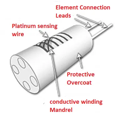
This is because of the resistance of the wire changes due to mechanical stress. Laboratory-grade resistance thermometers used in calibration and standards laboratories eliminate this source of error by winding the resistance wire loosely around a non-conductive support structure. Although this type of RTD can be very accurate, it is fragile and not suitable for most industrial applications. Temperature up to 660°C can be sensed using this type of RTD
Coiled Element RTD
In coiled element RTDs, resistive wire is wound into small coils loosely placed in a ceramic mold and then filled with a non-conductive powder.
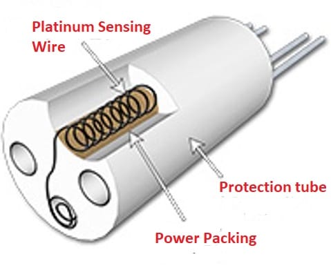
Resistance wire expands and contracts freely with temperature changes, minimizing errors due to mechanical stress. The powder improves the response time by increasing the rate of heat transfer to the coil. Coiled element RTDs are usually protected by a metal sheath when forming the RTD temperature sensor. Temperature up to 850 °C can be sensed using this type of RTD
Thin Film RTD
Thin Film RTD is produced on large scale and it also cost less compared to other types of RTD.
They have a fast response which is a big advantage in using thin-film RTD. The construction is such that a thin film of platinum is deposited on the ceramic base which makes thin-film RTD very small in size. The accuracy of thin-film RTD is very less.
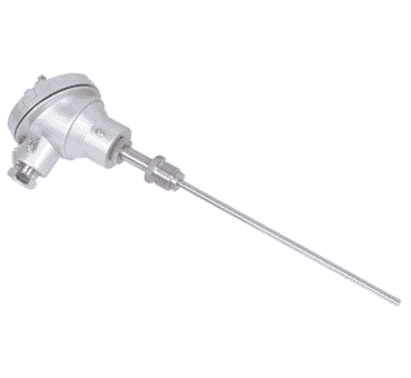
Sheathed RTD
Sheathed RTD is the most widely used RTD in industrial applications. The RTD sensing element Is placed inside a sheath which is typically Magnesium Oxide (MgO) and lead wires are extended from there.
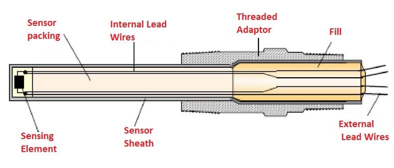
The RTD is usually installed inside a thermowell.
RTD vs Thermocouple which one to use?
- RTD is more accurate than the thermocouple, so if more accuracy is needed, definitely RTD should be used. Also, the repeatability of RTD is much more compared to that of thermocouples.
- RTD has a lower range as compared to the thermocouple i.e. RTD can measure up to 750°C while thermocouples have a large operating range up to 2300°C.
- The sensitivity of RTD is more compared to thermocouples and hence RTD can register small changes in temperature as compared to thermocouples.
- RTD has a low response time as compared to the thermocouple.
- The output of RTD is linear while that of thermocouple is non-linear
- Resistance temperature detectors are more expensive than the thermocouple i.e. RTD cost 2.5 to 3 times more than the thermocouple.
- RTD gives a stable reading for more time as compared to thermocouples. A thermocouple’s output tends to drift over time.
Hence it is clear that thermocouples are more economical than RTD but not as reliable as RTD.
Read Next: