The SAMA is an acronym for Scientific Apparatus Makers Association. The SAMA diagram is used in the plant that provides more detailed process diagrams. In another way, it is expressed as scientific apparatus (SAMA) of symbols and functional diagrams used for block functions and functional designations. The SAMA diagram assists in industrial processes where the binary symbology is extremely useful.
In industrial instrumentation and control, it is used a special system of symbols for the purpose of conveying in an easier and more specific way the information. This is indispensable in the design, selection, operation, and maintenance of the systems and control.
History – SAMA Diagram
- SAMA is a commercial association of manufacturers of scientific devices or scientific associations of appliance manufacturers.
- It was founded in 1918.
- Popular usage by so many members.
- SAMA dedicated areas are in the design, manufacturing, and distribution of instruments, apparatus, and equipment used for measurement, analysis, and control.
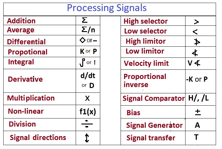
The complex control strategies are often documented using SAMA symbology diagrams. The standard symbols defined in the table below directly support the details of control signal processing.
The SAMA comprises seven sections
- Analytical instruments
- Measuring and testing instruments
- Laboratory apparatus
- Optical nuclear instruments
- Process Measurement and control instruments
- Furniture
- Equipment for scientific laboratories
The following are the processing signals of the SAMA diagram.
Why is SAMA Diagram popular?
The complex nature of the strategies used for the combustion control requires a notation that exceeds the Process Diagrams and ISA Standard Instrumentation (P&ID). The SAMA has developed such annotation and this is commonly used to define control strategies of combustion operations.
SAMA symbols have widespread use in the power generation industry because of the complexity of their control strategies. The SAMA method is most suitable for boiler functional diagrams because of the higher level of control-element details and the visualization they provide.
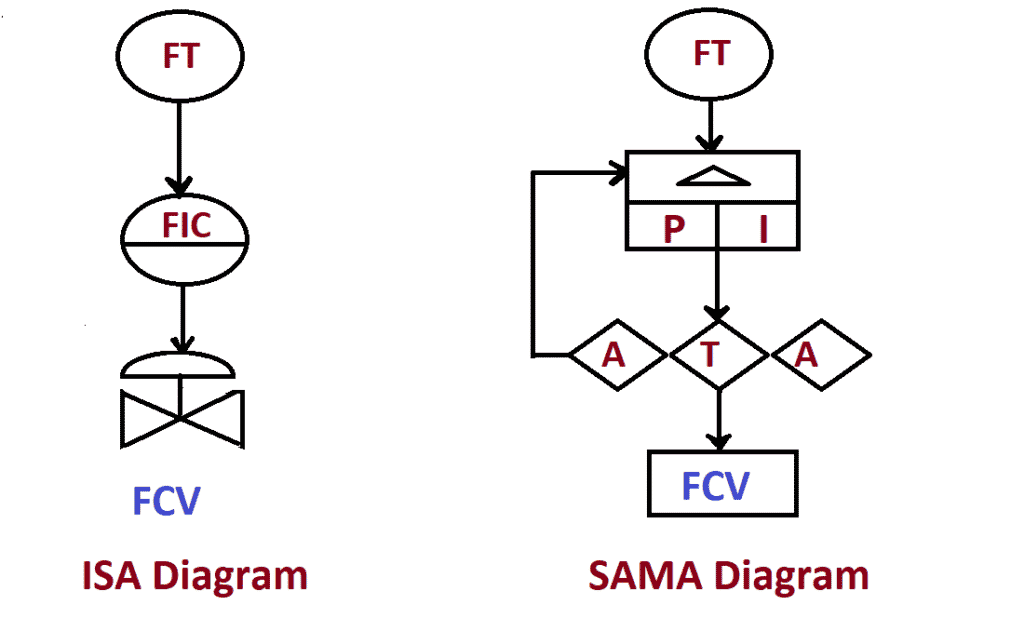
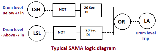
The SAMA diagram is very similar to the flow chart in appearance with symbols to represent different functions and is based on the operational requirement. The sequence in each of the instruments or functions of a loop is connected in a diagram and may reflect the logical operation shown as below.
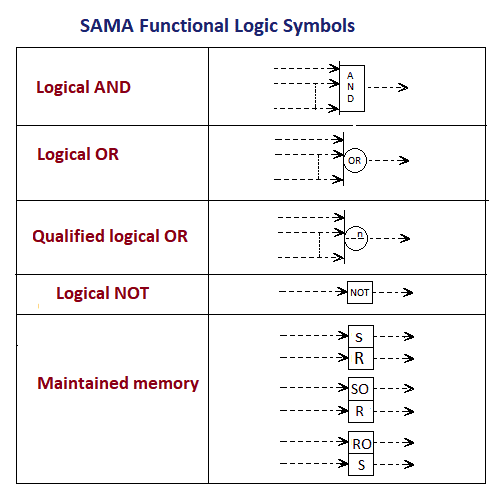
The SAMA functional logic symbols
SAMA Drawing
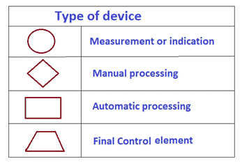
It consists of four forms, a series of letters for label information, and various mathematical control algorithms. These will combine to fully describe the logic of complex control. Below one is a typical ISA diagram and SAMA.