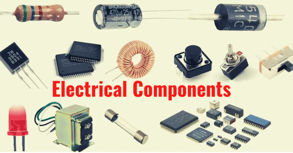
Introduction to Electrical Components- Electrical components are the basic building block of electrical & electronic circuits. Without the use of electrical components, it is impossible to build electric & electronic circuits. In this article, we will discuss important electrical devices.
Resistor
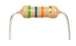
In an electronic & electrical circuit, the basic function of a resistor is to limit the current to a safe value so that the associated sophisticated parts can function properly without vulnerability. The current limiting depends on the value of the resistor. The higher valve resistor hinders more current flow compared to the lower valve resistor.
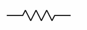
Symbol of Resistor used in an electrical circuit
The resistor is a passive two-terminal electrical component that resists the electric current. (Passive component means no external electrical supply needed). It controls the flow of electric current within a circuit. The resistance value is measured in Ohms.
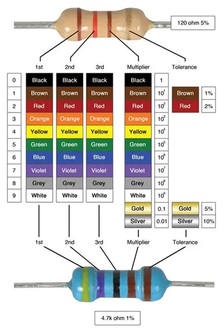
The color-coding shows the valve of resistance.
Variable Resistor
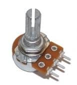
As its name suggests, a variable resistor is a device that we use where the variation of resistance is desirable. Variable resistor changes current in the circuit because of a change in the resistance. Generally, it has a knob called a pot to change the value of the resistor.
Symbol of Variable Resistor used in an electrical circuit
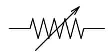
The variable resistor is used for dimming of lights, Changing the speed of fan, etc. It has three terminals, Two Fixed and One movable terminal.
Different types of Variable Resistor are Potentiometer, Rheostat, Thermistor
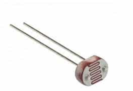
LDR (Light Dependent Resistor)
LDR is Light Dependent Resistor. It changes resistance according to the brightness of the light. A photoresistor (or light-dependent resistor, LDR, or photocell) is a light-controlled variable resistor. The resistance of an LDR decreases with increasing incident light intensity. In other words, we can say the device has a photoconductivity property.
Symbol of LDR used in an electrical circuit
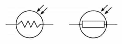
Resistance of LDR can be several megohms in darkness and then fall to a few hundred ohms in bright light.
It is used in automatic lights to switch on and off. A photoresistor can be applied in light-sensitive detector circuits, and light- and dark-activated switching circuits.
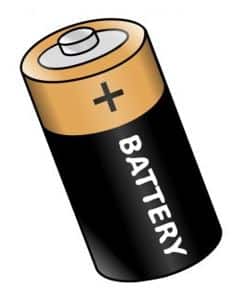
Introduction to Electrical Components–Battery
The battery is an electrochemical device. It has cathode and anode plates separated by an electrolyte that permits the passage of Ions between two electrodes.
Symbol of Battery used in an electrical circuit
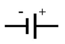
Two main types of batteries are Primary (Non-Rechargeable) and Secondary (Rechargeable) batteries. The further classifications are Alkaline and Lithium batteries.
It is available in different voltage capacities I.e., 1.5 V,9 V, etc.
Diode
A Diode is a device, which allows the current to flow only in one direction and blocks the current in the reverse direction. It is a Semiconductor device.
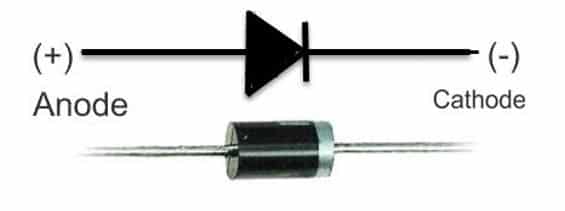
Types of Diodes are Signal Diode, Power Diode, Light Emitting Diode, Zener Diode.
We use a diode as Rectifier (Rectifier is a circuit that converts Alternating current to Direct current. Almost all household appliances work on Direct current. Therefore, AC to DC conversion is a must. It is also used in reverse current protection, logic gates, and voltage Spike suppression.
LED (Light Emitting Diode)
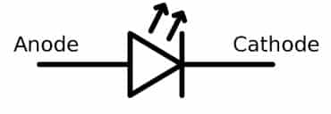
Light-emitting diode (LED) is known as LED. It emits light when current flows through it. It has two terminals-Positive terminal and a negative terminal. A bigger leg is the positive terminal and a shorter leg is the negative terminal. Therefore, it is important to identify its legs before connecting to the circuit.
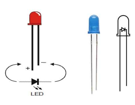
Symbol of LED used in electrical circuit
Aluminum Indium Gallium phosphide (AlInGaP) and Indium Gallium Nitride (InGaN) are the two most common semiconductors for LED technologies. The color of the LED depends on the type of semiconductor material used in its manufacturing.
Aluminum alloys are used to obtain red, orange, and yellow light, and indium alloys are used to get green and blue light. Also, slight changes in the composition of these alloys change the color of the emitted light.
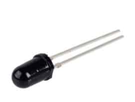
Introduction to Electrical Components–Photodiode
A photodiode is one type of light detector, used to convert the light into current or voltage based on the mode of operation of the device.
Symbol of Photodiode used in an electrical circuit
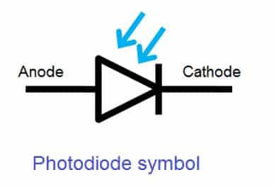
Photodiodes perform the opposite effect to LEDs. Instead of using electric current to cause electrons and holes to combine to create photons, photodiodes absorb light energy (photons) to generate electron-hole pairs, so creating an electric current flow.
The magnitude of Electromotive force generated directly depends on the intensity of the Incident Light. Thus, the intensity of the light is very important for the conduction of photodiode.
Photodiodes have wide application in fiber optics, solar panels, bar code scanners, Printers, & Cameras.
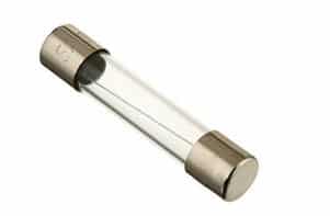
Fuse
An electrical fuse is a simple device used to interrupt an electrical circuit during overcurrent conditions due to short circuits and/or overload. An electrical fuse operates on the principle of the heating effect of electric current.
Symbol of Fuse used in an electrical circuit
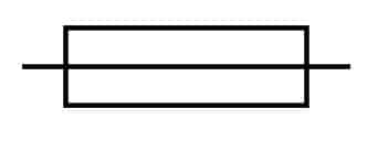
If more current flows in the circuit than the desired value, the wire melts and breaks the circuit. It protects the device from damage. Fuse has ratings as 3A, 5A,13A means thin wire will melt as 3A,5A, 13 A respectively.
We must use the fuse of a slightly higher current rating than the device’s full load current.
- If the device works at 3 A, use a 5 A fuse
- If the device works at 10 A, use a 13 A fuse
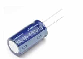
Introduction to Electrical Components–Capacitor
A capacitor is a passive two-terminal device that stores the electric charge when voltage is applied across its terminals. Thus, it allows alternating current to pass and blocks direct current.
Symbol of Capacitor used in an electrical circuit
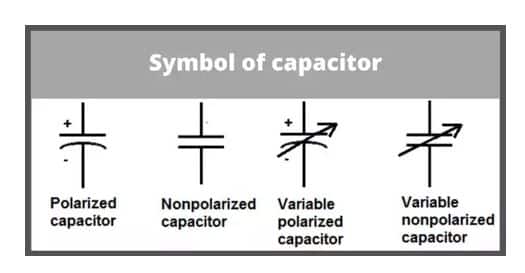
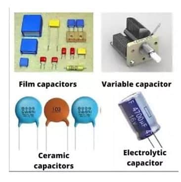
Types of capacitors are ceramic, electrolytic, film, and variable Capacitor. Electrolytic capacitors have a polarization property type while ceramic capacitors do not have polarization property.
We measure the capacitance value in Farad.
How to read value of Capacitor?
Ceramic capacitors encoding consists of 1-3 digits.
If the capacitor code consists of only 1 or 2 digits, it simply shows their capacitance value in Picofarads (pF). For example, if a ceramic capacitor has a code ‘9’, then its value is 9pF. If the capacitor has a code 57, then the capacitance value is 57 Picofarads.
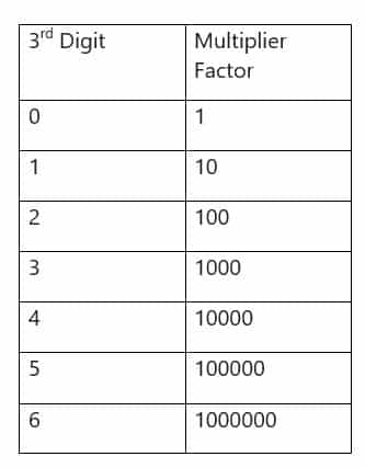
A 3 digit capacitor code shows
- The first two digits shows the capacitance value in pF,
- Third digit is a multiplier factor for the first two digits.
For Example,
104 is written on Capacitor. It means, 10 pF x 10000 = 100000 pF. It is possible to print the capacitance value on its body if enough space is available. Thus, by seeing the code on the capacitor, we can find the capacitance value.
Variable Capacitor
Variable capacitors are just as they named. Their capacitance will change while changing the plate physically and electrically. It is possible to change the capacitance by tuning, trimming & mechanically. Generally, these capacitors have applications in radio & TV receivers.
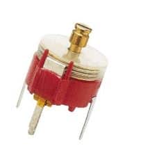
Symbol of Variable Capacitor used in an electrical circuit.
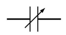
It has widespread application in tuning circuits.
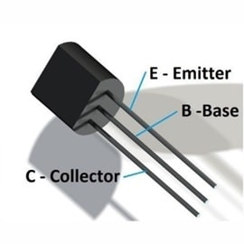
Introduction to Electrical Components-Transistor
A transistor is a semiconductor device. Generally, it has wide application in signal switching & amplifying application.
Symbol of Transistor used in an electrical circuit
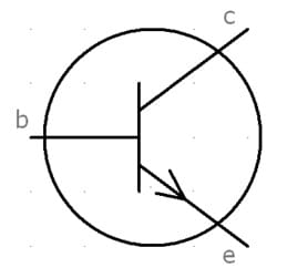
A transistor is a three-terminal device. Namely,
- Base: This is responsible for switching on or off the transistor.
- Collector: This is the positive lead.
- Emitter: This is the negative lead.
The two main types of Transistors are NPN and PNP.
Integrated Circuit (IC)
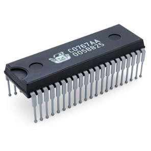
An integrated circuit (IC) is a semiconductor wafer on which thousands or millions of tiny resistors, capacitors, and transistors exist. Thus, it is possible to make the circuit compact by the use of IC.
There are various ICs for various purposes with different Symbolic notifications in the electric diagrams.
Examples of ICs are AND, OR, IC 741, etc.
Read Next: