Induction motors have a low power factor at no load because they draw a large magnetizing current to create the magnetic field, while the actual useful power (active power) is very small. This magnetizing current is mostly inductive, which makes the current lag far behind the voltage, leading to a poor power factor.
The power factor of an induction motor is very low, in the range of 0.1 to 0.3 when the motor runs at no load.
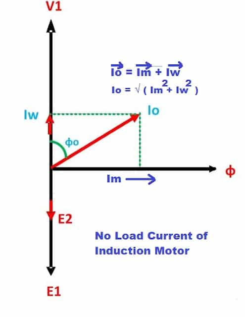
No-Load Current of Induction Motor
There are two components of the no-load current- Magnetizing Current(Im) and Working Current(Iw) or no-load loss component current. The motor takes magnetizing current for setting up the magnetic field in the air gap.
The magnetizing current remains constant if the voltage and frequency are constant. The magnetizing current lags the stator voltage (V1) by 90°. The magnetizing current is a watt-less current.
The magnetizing current(Im) does not depend on the loading on the motor, and, practically, the magnetizing current has a constant value in the induction motor.
The motor also draws the no-load loss current(Iw) because of the eddy current and hysteresis loss. The no-load losses in an induction motor are fixed types of loss. Therefore, the no-load loss current component(Iw) remains constant.
The no-load loss current(Iw) does not depend on the loading of the motor. Thus, the no-load current(Io) is equal to the vector sum of the magnetizing current(Im) and working current(Iw). The phasor diagram of no-load current is shown below.
Load Current in Induction Motors
The load current of an induction motor depends on the loading on the motor and varies according to the percentage loading on the induction motor. The load current varies as the loading on the motor is varied.
When the motor is operated on no load, the motor draws minimal load current. The load current is drawn to meet the torque requirement to drive its rotor.
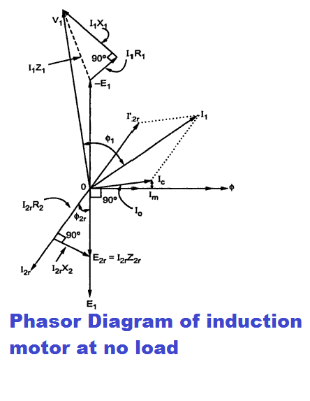
The magnetomotive force(MMF=NI) produced in the rotor is phase opposition in the MMF produced in the stator. The phasor diagram of the motor at no load is given below.
Power Factor of Induction Motor at No Load
At no load, the rotor current is I2. The phase angle between the I2 and rotor-induced voltage E2 is more; hence, the power factor of the rotor circuit is low. The equivalent magnitude of the rotor current is reflected in the stator side.
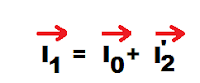
The current reflected in the stator side is known as the referred current. The total stator current of the motor is equal to the vector sum of the rotor-referred current plus the no-load current.
At no load, the Cosine of the phase angle between the stator current(I1) and the stator applied voltage(V1) is the power factor of an induction motor.
The angle between the voltage V1 and current I1 is large when the induction motor runs at no load. Therefore, the power factor of the motor is about 0.1 to 0.3.
Effect of Loading on Power Factor
The power factor of the motor gets improved with increased loading on the motor. With increased loading, the impedance of the rotor circuit decreases, the rotor draws less reactive current, and thus, the power factor of the motor improves.
Example: Rotor Power Factor at Different Loads
Let us take an example of how the rotor power factor improves with increased loading on the induction motor.
Let the rotor resistance be 0.1 Ohm, rotor reactance is 0.672 Henery, and the full load slip of the motor is 4%. The calculation of the rotor power factor at different loadings on the motor is shown in the table below.
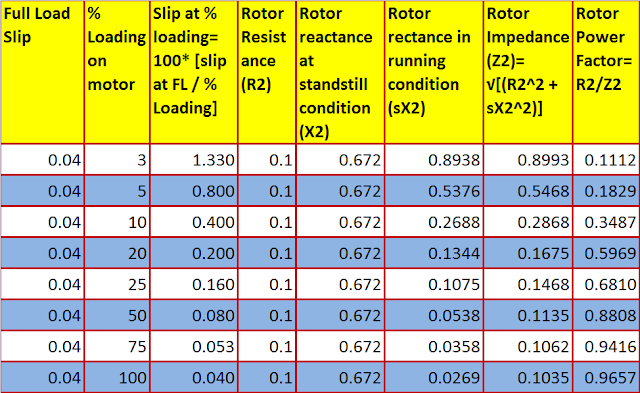
From the above table, it is very clear that the power factor of an induction motor is poor when the motor is at no load or light load. The low power factor is because of high rotor reactance at lower loading. The rotor reactance value decreases with increased loading on the induction motor.
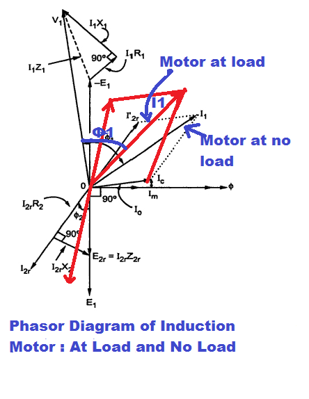
The phasor diagram of an induction at load is given below.
Related Articles:
2 thoughts on “Why Induction Motor Has Poor Power Factor at No Load”