An impulse line conveys process pressure output accurately from the pipe tapping point to the transmitter. An Impulse line is a part of the process instrumentation loop. The impulse line connections between the process tapping point and the transmitter play a vital role in measurement accuracy.
Thus, the accuracy of process measurements depends on the correct functioning of each component of the process instrumentation loop.
We must take safety and accuracy as a priority when measuring pressure, flow, or level in the process.
Purpose of impulse lines
Impulse lines play a vital role in measuring the process parameters. It is often unclear whether the impulse line conveys process pressure properly or not.
If the impulse line is not functioning properly, and the focus is only on the transmitter, the accurate process variables will be virtually impossible.
Process Isolation Valve (PIV)
The process isolation valve (PIV), also called the root valve, is the first valve outside the process line. The PIV is generally a needle valve, simple gate valve, or ball valve.
The best option for pressure transmitter isolation is a Double Block and bleed valve (DBB). It consists of two isolation valves and a vent valve between them.
The main reason for using a DBB is security. If the process instrumentation line needs to be shut down for maintenance, the two isolation valves are closed, and the vent valve is opened. And if, for some reason, the first isolation valve had any leakage, DBB provides safety for high-pressure process lines.
Impulse line material
For most applications, stainless steel SS 304, SS 316, or a higher metal alloy is preferred due to its corrosion resistance. Still, many industrial plants continue to use carbon steel process interface valves, piping, and even some manifolds.
The process fluid, environmental conditions, and system pressure/temperature generally determine the selection of alloys.
Process interface valves (PIVs), impulse lines, and manifolds – there are critical material choices that can influence accuracy.
Impulse line size
We use line sizes from 4 mm to 25 mm depending upon the nature of the fluid and the distance of transmitter mounting. The smallest size impulse lines are suitable for unsteady flow.
As per ISO 2186: 2007 recommendations, the internal diameter of the impulse line must not be less than 6 mm. A 10 mm size is suitable in case of the likely occurrence of condensate from gas service where gas bubbles liberate from the liquid.
There are three main goals to keep in mind when laying impulse lines.
- Avoid corrosion, slag build-up, or clogging
- Reduce leak points
- Keep the temperature within a certain range or prevent freezing
Manifold block
The manifold block connects the impulse line at the transmitter end. It is a set of valves whose bodies are machined from a block of metal, usually stainless steel. It mounts on the side of the transmitter, and its function is critical as it allows isolation for calibration or maintenance of the transmitter.
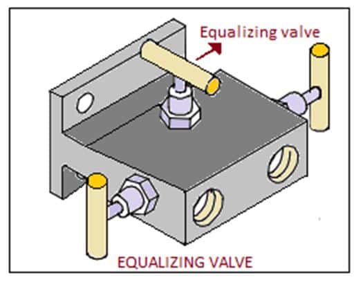
The quality and reliability of the manifold block are especially important. During calibration or normal operation, at least one of the valves remains closed. If the closure is not complete, the transmitter reading will not be accurate.
Slope of impulse line
The slope of the impulse line plays a vital role in transmitting process line fluid pressure. A slope of 80 mm per meter is ok. For gas and air service, a slope of more than 80 is suitable.
Avoiding the impulse line blockage
- Causes of blockages are freezing, waxing, and hydrate formation.
- In certain geographical locations, fluids in impulse lines freeze during winter, which is a common phenomenon. To avoid it, heat tracing by electrical means or steam is necessary.
- You must Prefer the minimum impulse line length. Short impulse lines give a fast response. It is suitable for pulsating flows.
- To avoid blockages, the impulse line minimum bend radius limit should be within its specified limit. The over-bending leads to blockages.
- The proper slope of the impulse line ensures no blockage. Therefore, in the design stage, the slope is a very important criterion.
Purging of impulse lines
Purging of impulse pipe is necessary to avoid freezing, plugging, and corroding. Impulse line purging is arranged in both ways. It is either by a temporary purging or setting up by a permanent purging line.
- Temporary purging is done only in case of blockage in impulse lines with a hose pipe. It is either by air or compatible process fluid that does not react with the process line.
- Permanent purging arrangement for the impulse line subjected to frequent blockage. For example, a transmitter in a boiler flue gas line.
Tapping Point Location
Followings are the preferred locations but are not mandatory.
Steam and Water Service
It is recommended to mount the instrument below the tapping point. This arrangement prevents entrapped gas bubbles and also reduces the temperature at the instrument end. There is no need for a high-pressure vent with this arrangement.
Vacuum Service
We locate the instrument above the source point so the impulse line becomes self-draining.
Air and Gas Services
The instrument mounting position is above the source point for self-draining of condensed moisture.
Preferred Location of Tapping Point on the Pipe
The impulse piping configuration depends on the specific measurement application. Theoretically, we can do the tapping at any position in a circular pipe cross-section in the plane, but there are certain criteria for locating the tapping points based on various services.
Steam flow measurement (condensate steam) or clean liquids
Sockets are mounted on the side of the process line. The transmitter is mounted below or to the side of the outlets by impulse lines. The drain/vent valve is mounted facing forward above.
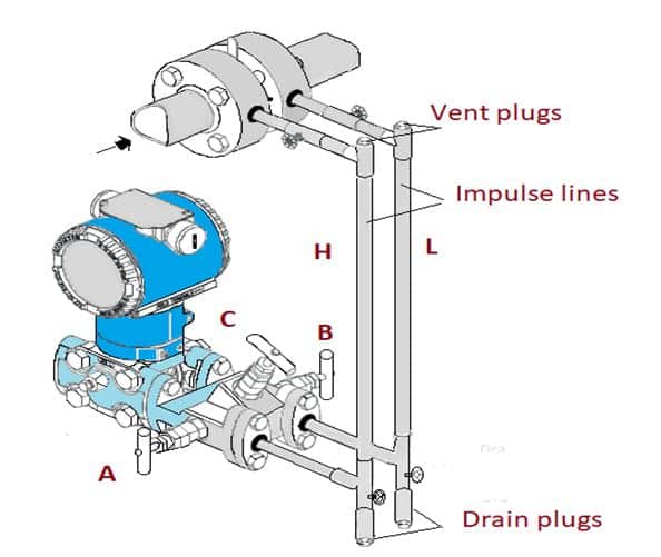
— In the case of steam application, required to fill in the section vertical connection lines with a fluid compatible through the filling tees.
The process liquid has to enter the primary of the transmitter.
- Open equalizing valve (C).
- Close the low-pressure (B) and high-pressure (A) valves.
- Open gate valves
- Slowly open the high-pressure valve (A) to admit the process fluid on both sides of the manifold block.
- Slightly drain or Vent to escape entrained gas bubbles, then close the valves.
- Open valve (B) and close equalizing valve.
Gas or liquid flow measurement (with solids in suspension)
The sockets are required to be mounted at the top or side of the line. The transmitter is mounted above the sockets by impulse lines.
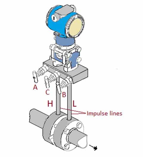
The process liquid must enter the primary of the transmitter.
- Open equalizing valve (C).
- Close the low-pressure (B) and high-pressure (A) valves.
- Open gate valves.
- Slowly open the high-pressure valve (A) to admit the process fluid on both sides of the manifold block.
- Slightly drain or Vent to escape entrained gas bubbles, then close the valves.
- Open valve (B) and close equalizing valve.

Related Articles: